1395 Connection Guide Circuit Board Jumper - Allen

1395 Connection Guide
Circuit Board Jumper Connections and Control Connections
Circuit Board Jumper Connections
There are several jumpers located on different boards in the 1395 that are used to configure the drive for a specific application.
J1 Jumper on PSI/Switcher
3
4
1
2
1.
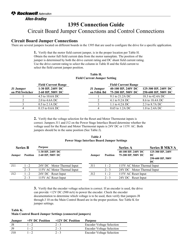
Verify that the motor field current jumper, is in the proper location per Table H.
Obtain the motor full field current data from the motor nameplate. The position of the jumper is determined by both the drive current rating and DC shunt field current rating.
Use the drive current rating to select the column in Table H and the field current to select the field current jumper position.
Field Current Range
1-30 HP, 240V DC
2-60 HP, 500V DC
4.5 to 10.6A DC
2.0 to 4.6A DC
0.5 to 2.1A DC
0.15 to 0.6A DC
Table H.
Field Current Jumper Setting
J1 Jumper on Fdbk Bd
3
4
1
2
Field Current Range
40-100 HP, 240V DC
75-200 HP, 500V DC
9.1 to 21.2A DC
4.1 to 9.2A DC
1.1 to 4.2A DC
0.65 to 1.2A DC
125-300 HP, 240V DC
250-600 HP, 500V DC
18.3 to 42.4A DC
8.6 to 18.4A DC
2.3 to 8.7A DC
1.0 to 2.4A DC
Series B
Jumper Position
J11
J12
1 - 2
2 - 3
1 - 2
2 - 3
2.
Verify that the voltage selection for the Reset and Motor Thermostat inputs is correct. Jumpers J11 and J12 on the Power Stage Interface Board determine whether the voltage used for the Reset and Motor Thermostat inputs is 24V DC or 115V AC. Both jumpers should be in the same position (See Table J).
Table J
Power Stage Interface Board Jumper Settings
Purpose
1-30 HP, 240V DC
2-60 HP, 500V DC
24V DC Motor Thermal Input
115V AC Motor Thermal Input
24V DC Reset Input
115V AC Reset Input
Jumper Position
J11
J12
1 - 2
2 - 3
1 - 2
2 - 3
Series A
40-100 HP, 240V DC
75-200 HP, 500V DC
Series B MKVA
125-300 HP, 240V
DC
250-600 HP, 500V
DC
115V AC Motor Thermal Input
24V DC Motor Thermal Input
115V AC Reset Input
24V DC Reset Input
3.
Verify that the encoder voltage selection is correct. If an encoder is used, the drive can provide +12V DC (500 mA) to power the encoder. Check the encoder documentation to determine which voltage is to be used, then verify that jumpers J8 through J 10 on the Main Control Board are in the proper position. See Table K for jumper settings.
Table K.
Main Control Board Jumper Settings (connected jumpers)
Jumper +5V DC Position +12V DC Position Purpose
J8 1 - 2 2 - 3 Encoder Voltage Selection
J9
J10
1 - 2
1 - 2
2 - 3
2 - 3
Encoder Voltage Selection
Encoder Voltage Selection
J14 1 - 2
2 - 3
EE Write Enabled
EE Write Disabled
Note: The encoder jumpers J8 - J10 are set for the voltage output of the encoder.
ATTENTION: Jumpers J8 through J10 must all be in the same position. To guard against possible damage to the Main Control
Board, assure that jumpers are positioned correctly for your application.
Table K.
Main Control Board Jumper Settings (non connected jumpers)
Jumper +5V DC Position
J12
J13
J15
No Connection
No Connection
No Connection
+12V DC Position
No Connection
No Connection
No Connection
Purpose
Internal Use, Do Not Use
Internal Use, Do Not Use
Internal Use, Do Not Use
ATTENTION: No connections should be attempted on jumpers J12, J13, and J15. Making connection at these jumpers could cause damage to the Main Control Board.
Control Connections
A user installed 115V AC power supply is required to power the Power Stage Interface Board, power supply, DC contactor and fans.
It is recommended that a control transformer be used to provide the 115V AC supply. Refer to Table L for current requirements and
Figure 13 or Figure 14 for connection information.
Table L.
115V AC Control Circuit Current Requirements
230V Drive
460V Drive
Total Sealed Current
Total Inrush Current
1-15 HP
2-30 HP
1.230
2.270
20-30 HP
40-60 HP
2.083
3.600
40-50 HP
75-100 HP
2.283
8.150
60-75 HP
125-150 HP
2.910
12.790
100 HP
200 HP
3.100
16.150
125 to 600 HP drives require a 750 VA control transformer. The current required for the 115V discrete inputs and outputs must be added to the control circuit current requirement for proper sizing of the control transformer.
Input and output signals can be 24V DC, but will require a separate 24V DC power supply in addition to basic 115V AC control circuit requirement
All control wiring to external devices except for contactor control is terminated in the drive at terminal block TB3. Signal definitions for terminals 1-20 have been predetermined and are independent of drive application. Figure 12 illustrates these terminals with their signal definitions.
TB3 is attached to a mounting rail at the bottom of the drive chassis. It provides a wiring connection for customer supplied control and signal devices, along with encoder interface and auxiliary peripheral devices.
Additional individual terminal blocks can be attached to the mounting rail to meet application requirements. These additional terminal blocks are supplied when using an adapter board, for I/O to and from the drive.
Control Wiring Procedure
1.
Wire Encoder to TB3. If an encoder is used, refer to the encoder instruction manual for proper wiring to the drive a) Terminals 19 and 20 connect to differential encoder output A (NOT) and A.
b) Terminals 17 and 18 connect to differential encoder output B (NOT) and B.
c) Terminals 15 and 16 are reserved for future use and are not to be used.
d) Terminal 14 provides + 12V DC (500 mA max.) power to the encoder. Some encoders limit the + 12V DC supply internally to
+ 5V DC for the output. Consult the encoder documentation to determine whether the encoder output signal level is + 12 or + 5V
DC. Jumpers J8 - J10 on the Main Control Board must be properly positioned to correspond to the encoder output voltage.
e) Terminal 13 provides connection to the encoder supply voltage common (ground).
f) The encoder shield must be connected to the encoder case (ground).
g) The encoder cable must be separate from armature and field leads, refer to Table B.
h) Maximum encoder cable length is 500 feet (150 meters). For other lengths contact your Allen-Bradley Sales Representative.
ATTENTION: The Start/Stop circuitry in this drive is composed of solid-state components. If hazards due to accidental contact with moving machine components or unintentional flow of liquid, gas or solids exist, a hardwired Stop circuit must be used with this drive. For 115V AC control, this circuitry may be added at terminals 4 and 5 of TB3.
ATTENTION: If Dynamic Braking is used as an alternative stopping method, Do Not use a hard-wired Stop devicethat removes AC line power. This will de-energize the shunt field, causing a loss of the DB effect and the motor will coast to a stop. Hazards to personnel may exist if the machine is allowed to coast to a stop.
ATTENTION: The user has the ultimate responsibility to determine which stopping method is best suited to the application and will meet applicable standards for operator safety.
Figure 12
TB3 Terminal Descriptions
2.
Wire Emergency Coast Stop Circuit (ECOAST).
The drive has the capability to accept an ECOAST input from either a 24V DC or 115V AC contact. The contact must be normally closed and will typically be a Stop pushbutton. Refer to the following paragraphs, Figure 12 and Table M for connection information.
If a 24V DC ECOAST is desired, the contacts of the ECOAST device must be wired between terminals 9 & 11 of TB3. Jumpers must then be connected between terminals 4 & 5 and 10 & 12 of TB3.
If a 115V AC ECOAST is desired, the contacts of the ECOAST device must be wired between terminals 4 and 5 of TB3.
Jumpers must then be connected between terminals 9 & 11 and 10 & 12 of TB3.
Table M.
ECoast Connections
TB-3 Terminals
4 and 5
9 and 11
10 and 12
24V DC
ECOAST Input
115V AC
Jumper N.C. Contact Device
N.C. Contact Device Jumper
Jumper Jumper
ATTENTION: Applying improper input voltage could damage the Power Stage Interface Board. Jumpers J11 and J12 on the Power
Stage Interface Board must be set for the proper input voltage before applying power to these inputs
3.
Wire the Motor Thermostat Circuit. Terminal TB3-2 is used to receive either a 24V DC or 115V AC input (derived from an external voltage source) when the motor thermostat contact is closed. The contacts of the motor thermostat must be N.C
The drive interprets a high voltage at TB3-2 as a normal expected condition Refer to Figure 12 for further connection information.
4.
Reset/Normal Stop.
This input is programmable to provide either a System Reset function or a Normal Stop function. It accepts a 115VAC or
24VDC input voltage. System Reset Select (parameter 620) determines which function this input provides.
The System Reset function requires a N.O. operator device which closes to cause a reset. A reset input causes the drive to perform a power-up sequence. Any data not previously stored in EEPROM memory will be lost.
The Normal Stop function requires a N.C. operator device When opened, the drive will stop (the type of stop is determined by
Param 624). This may be used to provide an additional stop to the drive. The voltage used must be the same as the voltage supplied for the motor thermostat input.
IMPORTANT:
The 24V DC provided at TB3 - 11 and 12 must only be used for the 24V DC ECOAST circuit.
Figure 13
115V AC Input and Contractor Control Connections -
1 to 30 HP, 230VAC; 2-60HP, 460VAC
5.
Wire External drive Ready Indicator. Terminals TB3-7 and 8 provide connection to the output contact of the Ready/Fault relay located on the Power Stage Interface Board. The contacts are rated for 1A at 24V DC or 0.6A at 115V AC.
6.
Wire 115V AC Supply Voltage. It is recommended that the user ground the 115V secondary of the transformer. The drive
Does Not derive its own control voltage. Therefore, 115V AC must be supplied to the drive from an external source. A control transformer having a primary of 230V or 460V, based on the drive rating, and a secondary of 115V is recommended. Primary and secondary must be fused to meet NEC code. Fuse type FRN and FRS are recommended
Terminal Connections for the different ratings are outlined in Table N.
Table N.
115VAC Connections
Drive Rating
1 - 30 HP 230VAC
2 - 60 HP 460VAC
60 - 100 HP 230VAC
75 - 200 HP 460VAC
125 - 300 HP 230VAC
250 - 600 HP 460VAC
115V AC Input Connection
TB2 - 2 and 3 (see Fig. 13)
TB2 - 4 and (see Fig. 14)
TB5 - 4 and 5 (see Fig. 15)
Figure 14
115V AC Input and Contactor Connections-
40-100 HP on 230VAC Series A; 75-200 HP on 460VAC Series A
7.
Wire External Contactor Control Contacts. Terminals TB2 or TB5 (depending on horsepower rating) provide connection to the external 115VAC control voltage used to energize the Main Contactor Ml as follows:
Terminal TB2-1 1-30HP 230VAC
2-60HP 460VAC
Terminal TB2-3
Terminal TB5-6&7
1-30HP 230VAC
2-60HP 460VAC
125-300HP 230VAC
250-600HP 460VAC
The 115V AC control voltage enters the drive and is controlled by the pilot relay (PR). If it is desired to control the Ml coil voltage using contacts external to the drive (in addition to the pilot relay), the external contacts must be wired in series with the 115V AC supply voltage before entering the drive at either TB2-1, TB2-3 or TB5-4 . In most applications, external contacts are not used, therefore, 115VAC is supplied directly to TB2 or TB5 as follows:
Terminal TB2-2
Terminal TB2-4
1-30HP 230VAC
2-60HP 460VAC
1-30HP 230VAC
2-60HP 460VAC
Terminal TB5-4 125-300HP 230VAC
250-600HP 460VAC
Figure 15
115 V AC Input and Contactor Control Connections
125 to 300 HP, 230VAC; 250 to 600HP, 460VAC
8.
Terminals TB2 or TB5 (depending on horsepower rating) are used to allow the drive to be operated with external control of the contactor as follows:
Terminal TB2-6&7 1-30HP 230VAC
2-60HP 460VAC
Terminal TB2-8&9
Terminal TB5-8&9
1-30HP 230VAC
2-60HP 460VAC
125-300HP 230VAC
250-600HP 460VAC
IMPORTANT:
If an external control of the contactor is not used, place a jumper across the terminals as outlined in Table
O.
Table O.
External Contactor bypass jumpers
Drive Rating l - 30 HP 230VAC
2 - 60 HP 460VAC
60 - 100 HP 230VAC
75 - 200 HP 460VAC
125 - 300 HP 230VAC
250 - 600 HP 460VAC
115V AC Input Connection
TB2 - 6 and 7
TB2 - 8 and 9
TB5 - 8 and 9
9.
Connect Programming Terminal. Connect the 9 pin D-style connector of the Programming Terminal to the D-style connector (labeled DHT) mounted on the TB3 mounting rail. Refer to the Programming Terminal Installation and
Operation Manual for further details.


