1365 Troubleshooting Guide
advertisement

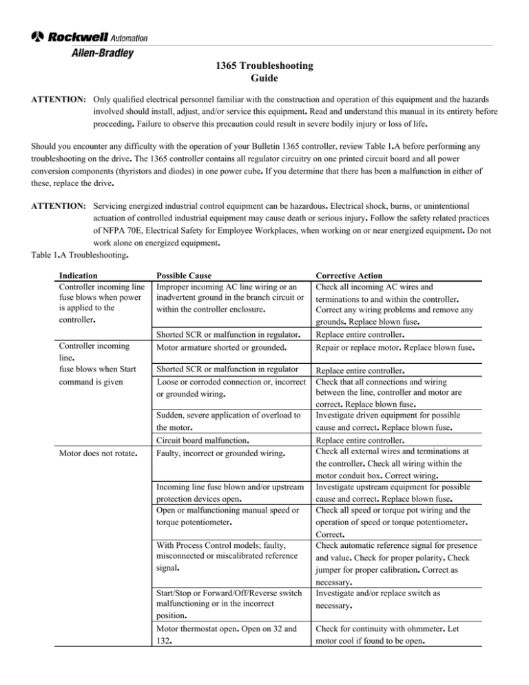
1365 Troubleshooting Guide ATTENTION: Only qualified electrical personnel familiar with the construction and operation of this equipment and the hazards involved should install, adjust, and/or service this equipment. Read and understand this manual in its entirety before proceeding. Failure to observe this precaution could result in severe bodily injury or loss of life. Should you encounter any difficulty with the operation of your Bulletin 1365 controller, review Table 1.A before performing any troubleshooting on the drive. The 1365 controller contains all regulator circuitry on one printed circuit board and all power conversion components (thyristors and diodes) in one power cube. If you determine that there has been a malfunction in either of these, replace the drive. ATTENTION: Servicing energized industrial control equipment can be hazardous. Electrical shock, burns, or unintentional actuation of controlled industrial equipment may cause death or serious injury. Follow the safety related practices of NFPA 70E, Electrical Safety for Employee Workplaces, when working on or near energized equipment. Do not work alone on energized equipment. Table 1.A Troubleshooting. Indication Controller incoming line fuse blows when power is applied to the controller. Controller incoming line. fuse blows when Start command is given Motor does not rotate. Possible Cause Improper incoming AC line wiring or an inadvertent ground in the branch circuit or within the controller enclosure. Shorted SCR or malfunction in regulator. Motor armature shorted or grounded. Shorted SCR or malfunction in regulator Loose or corroded connection or, incorrect or grounded wiring. Sudden, severe application of overload to the motor. Circuit board malfunction. Faulty, incorrect or grounded wiring. Incoming line fuse blown and/or upstream protection devices open. Open or malfunctioning manual speed or torque potentiometer. With Process Control models; faulty, misconnected or miscalibrated reference signal. Start/Stop or Forward/Off/Reverse switch malfunctioning or in the incorrect position. Motor thermostat open. Open on 32 and 132. Corrective Action Check all incoming AC wires and terminations to and within the controller. Correct any wiring problems and remove any grounds. Replace blown fuse. Replace entire controller. Repair or replace motor. Replace blown fuse. Replace entire controller. Check that all connections and wiring between the line, controller and motor are correct. Replace blown fuse. Investigate driven equipment for possible cause and correct. Replace blown fuse. Replace entire controller. Check all external wires and terminations at the controller. Check all wiring within the motor conduit box. Correct wiring. Investigate upstream equipment for possible cause and correct. Replace blown fuse. Check all speed or torque pot wiring and the operation of speed or torque potentiometer. Correct. Check automatic reference signal for presence and value. Check for proper polarity. Check jumper for proper calibration. Correct as necessary. Investigate and/or replace switch as necessary. Check for continuity with ohmmeter. Let motor cool if found to be open. Motor does not rotate. (Continued) Drive will not go to zero speed or torque. Motor does not reach top speed or deliver rated torque. Unstable speed or poor regulation when applied as an armature voltage Incorrect speed with tachometer feedback. Motor runs at maximum uncontrolled speed with tachometer feedback. Open circuit between terminals 132 and 35. Either a jumper or normally closed remote stop device must be connected between these two terminals in order for the drive to operate. Current feedback jumper set lower than applied motor horsepower. ATTENTION : Do not depend on the minimum position of the speed or torque setting pot to stop the motor. In the minimum position, the controller and motor are still energized. Noise, improper wiring, power line disturbances, malfunctioning components, or mechanical binding may cause the drive to restart unexpectedly. Failure to observe this precaution could result in bodily injury. Controller faulty. Low line voltage. Repair switch or insert jumper as required. With Process Control models, improperly set maximum speed pots. With Process Control models, reference signal producing less than expected maximum value. Overload. Improper position jumper. Reset maximum speed pots. Faulty circuit board. Incorrectly set IR drop compensation pot. Faulty circuit board. Improper feedback selection at J3. DC tachometer polarity not correct for given direction of motor rotation, 419 negative with respect to 519. Open field for voltage Regulators only. No DC tachometer output signal. Motor speed unstable with changing load. (Tach Feedback only) IR drop compensation pot not set at zero (CCW). Recheck and reset as necessary. Follow the instructions provided in this manual to configure the drive for zero speed (J201: Minimum Speed Disable). Replace entire controller. Check for rated line voltage and correct if not within 10% of the input voltage rating. Adjust source of automatic reference signal or proper output signal range. Check for cause of overload and correct. Check and reconnect jumper(s) as necessary: • J200: Tach Scaling Jumper • J3: Controller Output Current Jumper Replace entire controller. Readjust IR drop compensation pot. Check tachometer. Replace entire controller. Check J3 for proper feedback selection and reposition as required. Verify DC tachometer polarity and lead connection. Measure motor field resistance from drive and connect the voltage field as required. Verify tachometer voltage. Verify tachometer coupling. Set IR drop compensation pot to zero (CCW). • Spare Parts: The following spare parts are available: 1365-OP Kit includes: - Speed Pot (P/N 608870-91r) - Start/Stop Switch (P/N 49869-17a) - Run Jog or Auto/Manual switch (P/N 49869-20a) Fuse Kit For open chassis: 1365-Fu 1 For NEMA 4/12: 1365-Fu 2


