Measuring Impedance and Frequency Response of Guitar Pickups
advertisement

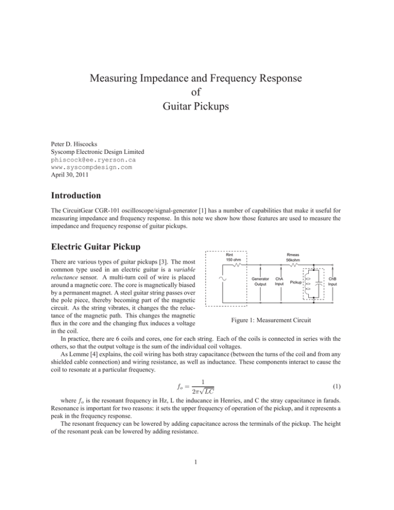
Measuring Impedance and Frequency Response of Guitar Pickups Peter D. Hiscocks Syscomp Electronic Design Limited phiscock@ee.ryerson.ca www.syscompdesign.com April 30, 2011 Introduction The CircuitGear CGR-101 oscilloscope/signal-generator [1] has a number of capabilities that make it useful for measuring impedance and frequency response. In this note we show how those features are used to measure the impedance and frequency response of guitar pickups. Electric Guitar Pickup Rint Rmeas 150 ohm 56kohm There are various types of guitar pickups [3]. The most common type used in an electric guitar is a variable reluctance sensor. A multi-turn coil of wire is placed Generator ChA ChB Pickup Input Output Input around a magnetic core. The core is magnetically biased by a permanent magnet. A steel guitar string passes over the pole piece, thereby becoming part of the magnetic circuit. As the string vibrates, it changes the the reluctance of the magnetic path. This changes the magnetic Figure 1: Measurement Circuit flux in the core and the changing flux induces a voltage in the coil. In practice, there are 6 coils and cores, one for each string. Each of the coils is connected in series with the others, so that the output voltage is the sum of the individual coil voltages. As Lemme [4] explains, the coil wiring has both stray capacitance (between the turns of the coil and from any shielded cable connection) and wiring resistance, as well as inductance. These components interact to cause the coil to resonate at a particular frequency. 1 √ (1) 2π LC where fo is the resonant frequency in Hz, L the inducance in Henries, and C the stray capacitance in farads. Resonance is important for two reasons: it sets the upper frequency of operation of the pickup, and it represents a peak in the frequency response. The resonant frequency can be lowered by adding capacitance across the terminals of the pickup. The height of the resonant peak can be lowered by adding resistance. fo = 1 Inductance Measurement: LC Meter The inductance of the pickup can be measured with an LC meter. Typical inductance for a guitar pickup is in the 1 to 10 Henry range, so make sure the meter can measure to at least 20 Henries. I used an old Mastech M-6243 LC Meter for these measurements. A newer model, the Mastech MY6243 only goes to a maximum value of 2 Henries, so it’s not useful for this. That said, I’d be wary of the value measured by an LC meter. For example, my M-6243 shows a value for inductance of 9.6H. The resonance method, described below, gives 8.026H. I have a lot more confidence in the resonance method. You can see the waveforms on the oscilloscope, so you know that some non-linearity in the coil is not affecting the measurement1 . (a) Below Resonance Measurement Circuit Figure 1 shows the inductance measurement circuit, using a signal generator and dual trace oscilloscope. The pickup is shown as an inductance in parallel with its internal stray wiring capacitance. The CGR-101 generator has an internal resistance of 150Ω. The output is connected to channel A of the oscilloscope. Resistor Rmeas and the pickup inductance form a voltage divider, where the voltage across the inductor is measured by channel B of the oscilloscope. Ideally, Rmeas should be much larger than the maximum impedance of the pickup. However, for determining the resonant frequency of the pickup and the pickup inductance, it’s not critical. I used 56kΩ. Roughly speaking, the channel A voltage represents the current in the circuit, channel B the voltage across the inductor. At low frequencies, the pickup behaves as an inductor, and the inductor voltage leads the current. For an example, see the scope waveforms in figure 2. As the generator frequency is increased to resonance, the voltage and the current are in phase. Then, at high frequencies, the capacitance dominates and the voltage lags the current. We are interested in the resonant frequency, where the voltage and current are exactly in phase. Now we’ll show how that can be measured, using the Lissajous Figure method for precision. (b) At Resonance (c) Above Resonance Figure 2: Waveforms and Lissajous Figures 1 It also makes me suspicious that the older version of the meter measures to 20H, the newer version only to 2H. Maybe Mastech found the meter wasn’t that accurate on the highest range? 2 Here We Go Loop de Loop2: The Lissajous Figure The normal oscilloscope display is a plot of voltage (vertical) vs time (horizontal). However, it’s equally possible to plot the voltages of the two channel inputs against each other, and the result is quite useful. The result is an XY Plot or Lissajous diagram [5]. If the two signals are sine waves at the same frequency, the XY plot forms an ellipse. In the special case where the two signals are equal and 90◦ out of phase, the plot is a circle. Where the two signals are equal and in phase, the plot is an ellipse with a zero length minor axis, that is, a diagonal line at 45◦ . Why is this useful? In our application, the Lissajous figure is a very sensitive indicator of relative phase. At the resonant frequency of an LC circuit, the voltage and current are exactly in phase. If we plot voltage on one axis of the XY plot and current on the other axis, then the Lissajous figure will become an ellipse at frequencies above and below resonance, and a straight line at resonance. Figure 2 shows Lissajous figures being used to measure resonant frequency. In each diagram, the Lissajous figure is the black trace in the foreground. Above and below the resonant frequency, the Lissajous figure forms a loop. At resonance, it’s a diagonal straight line. Notice the voltage-vs-time waveforms in the background, and how their phase relationship changes as the Lissajous figure changes. Also notice that the frequency slider minimum and maximum values have been change from their defaults to 700 and 15,000 Hz, in order to have fine control over the search for the resonant frequency. This technique will work with any sine wave generator that covers the required frequency range, and oscilloscope that is capable of XY plots. The Syscomp CGR-101 is particularly convenient because it includes a generator with extremely precise frequency resolution, and an oscilloscope capable of XY plot. Inductance Measurement Example We’d like to use equation 1 to determine the inductance of the pickup, but to do so we need to know both the resonant frequency fo and the capacitance C. We don’t know the stray capacitance in the pickup, but we can avoid that problem if we put a known capacitance across its terminals. Capacitances in parallel add so if the known capacitance is much larger than the stray capacitance, the stray capacitance is insignificant. Rearranging equation 1 to solve for the inductance, we have: 2 1 1 (2) L= C 2πfo For C = 619pF, fo measures 2259 Hz, and equation 2 gives L = 8.027 Henries. For C = 6.62nF, fo measures 690.8 Hz, and equation 2 gives L = 8.026 Henries. Since these two measurements give very close results, the added capacitance must be much larger than the stray capacitance, as we planned. This method assumes that you know the added capacitance values fairly accurately, so there is still a use for the LC meter, if you have one. In my experience, the LC meter measurement of capacitance is usually fairly close. Moreover, a capacitor has a nominal value, and the measured value should be close to nominal: that’s another check on the reliability of the measurement. Or you can buy close-tolerance capacitors and rely on their nominal value. There is a bit of a compromise in the choice of the added capacitances. On the one hand, they have to be large enough to be much larger than the stray capacitance of the pickup. As a typical value, I found a stray capacitance of about 60pF, so the added capacitance should be at least ten times this. (Hence my choice of 619pF as the smaller of the capacitors I used in the measurement.) On the other hand, a very large capacitance results in a low resonant frequency. Very low frequency waveforms are less convenient to view and measure on the scope. 2A children’s song: see [2]. 3 Pickup Frequency Response: Driver Coil Rint To measure the pickup frequency response, we need to 150 ohm induce a signal voltage at various frequencies into the coil of the guitar pickup. That would be very difficult to ChB Generator ChA do by vibrating a string (or other metal piece) near the Input Output Input coil. However, we can inject a voltage by transformer action from another nearby driver coil. Driver Pickup Figure 3 shows the test circuit. The signal generator places an AC voltage across the driver coil terminals. The driver coil produces an alternating magnetic field, Figure 3: Pickup Frequency Response Test Setup which couples into the guitar pickup. The pickup then produces an output voltage, the magnitude and phase of which depend on its frequency response. In order to obtain meaningful results the drive coil must have a wider frequency response than the guitar pickup. The driver coil I used for this purpose came from my junkbox. I would guess it was originally used as the solenoid for a doorbell plunger. The coil itself is wound on a plastic form with an air core, resistance 129Ω, inductance 36.9mH. The low inductance compared to a guitar pickup suggests that the self-resonant frequency will be higher than a guitar pickup, and that turns out to be the case. Figure 4 shows the impedance curve for the driver coil, obtained with the test circuit of figure 1, using the Vector Network Analyser (VNA) feature of the CGR-101. Figure 4: Driver Coil Impedance The upper trace shows the magnitude of the driver coil impedance plotted against frequency, with the peak value at the resonant frequency. The lower trace shows the phase of the impedance with a phase transition through zero degrees at resonance (the feature we used in the Lissajous measurement)3. Based on this plot, the 3 Could you use this plot instead of the Lissajous measurement to determine the pickup inductance? Yes, however the Lissajous method gives a result that is accurate to four significant figures. The VNA method is useful for an overview, but the frequency scale has lower resolution. 4 self-resonant frequency of the driver coil is about 100kHz. A typical self-resonant frequency for a guitar pickup (which is roughly the maximum useful frequency of the pickup) is in the order of 6 to 8kHz. So the driver coil will not limit the frequency response test. Pickup Frequency Response: Results Figure 5 shows the amplitude and phase response of three different guitar pickups. At high frequency, all three pickups show the classic second-order low pass filter behaviour, with some peaking around the cutoff (resonant) frequency. The low frequency behaviour is visibly different, with pickup #1 exhibiting a distinct low frequency hump. It’s also clear that the response of pickup #2 drops off less rapidly at low frequencies than the response of pickup #1. Using this measurement technique, it would be possible to determine the effect of various resistor and capacitor loads on the frequency response. It would also be interesting to relate the shape of a response curve to the characteristic sound of a particular pickup. (a) Pickup #1 Conclusions • The Lissajous Figure display of the CGR-101 CircuitGear can be used to make very precise measurement of the guitar pickup inductance. • The Vector Network Analyser (VNA) feature is useful for a broad brush look at impedance vs frequency. • The VNA feature is well suited to the measurement of guitar pickup response over and beyond audio frequencies. (b) Pickup #2 Acknowledgement Special thanks to Jeff Callahan [6], for the loan of the guitar pickups and useful discussions on test methods. (c) Pickup #3 Figure 5: Pickup Responses 5 References [1] Syscomp Electronic Design Limited www.syscompdesign.com [2] Loop de Loop (or Looby Loo): http://kids.niehs.nih.gov/lyrics/looby.htm [3] Guitar Pickup http://en.wikipedia.org/wiki/Guitar_pickup [4] The Secrets of Electric Guitar Pickups Helmuth E. W. Lemme February 25, 2009 http://buildyourguitar.com/resources/lemme/ [5] Lissajous Curve http://en.wikipedia.org/wiki/Lissajous_figure [6] Jeff Callahan Guitars http://callahanguitars.com 6


