Model 450E Electronic Horn Installation and
advertisement
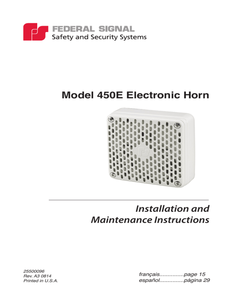
Model 450E Electronic Horn Installation and Maintenance Instructions 25500096 Rev. A3 0814 Printed in U.S.A. français...............page 15 español...............página 29 Industrial Systems 2645 Federal Signal Drive • University Park, IL 60484-3167 Tel: 708-534-4756 • Fax: 708-534-4852 Email: elp@federalsignal.com www.federalsignal-indust.com Contents Safety Message to Installers and Users........................................... 5 Unpacking the Horn........................................................................... 6 An Overview of the Model 450E........................................................ 6 Wiring the Horn................................................................................... 8 Mounting the Horn.............................................................................. 9 Non-Weatherproof Mounting.................................................. 10 Weatherproof Mounting.......................................................... 10 Weatherproof Panel Mounting................................................ 11 Getting Repair Service or Technical Assistance .......................... 12 Returning the Product for Credit.................................................... 12 Tables Table 1 Specifications......................................................................... 7 Figures Figure 1 Dimensions for panel-mounting............................................ 4 Figure 2 Dispersion characteristics for audible signal devices........... 7 Figure 3 Wiring connections............................................................... 9 Figure 4 Non-weatherproof mounting............................................... 10 Figure 5 Weatherproof mounting...................................................... 11 Figure 6 Weatherproof panel mounting............................................ 12 Model 450E Electronic Horn 3 Installation and Maintenance Instructions Figure 1 Dimensions for panel-mounting VERIFY DIMENSIONS OF TEMPLATE BEFORE USING (4) 3/16" (4.8 mm) 45.0° TYP. 3-5/8" (92.1 mm) TYP. 1-13/16" (46 mm) TYP. 3-3/8" (85.7 mm) TYP. 1-11/16" (42.9 mm) TYP. 1/2" (12.7 mm) TYP. © 2013 Federal Signal Corporation. All rights reserved. 4 Model 450E Electronic Horn OUTLINE OF CLEARANCE HOLE FOR DEVICE Installation and Maintenance Instructions Safety Message to Installers and Users People’s lives depend on your safe installation of our products. It is important to follow all instructions shipped with this product. This device is to be installed by a trained electrician who is thoroughly familiar with the National Electrical Code and/or Canadian Electrical Code and will follow the NEC and/or CEC Guidelines as well as all local codes. This horn should be considered a part of the warning system and not the entire warning system. The selection of the mounting location for this horn, its controls and the routing of the wiring are to be accomplished under the direction of the Facilities Engineer and the Safety Engineer. In addition, listed below are some other important safety instructions and precautions you should follow: • Read and understand all instructions before installing, operating, or maintaining this equipment. • Do not connect this unit to the system when power is on. • Optimum sound distribution will be severely reduced if any objects are in front of the horn. You should ensure that the front of the horn is clear of any obstructions. • All effective warning horns produce loud sounds which may cause, in certain situations, permanent hearing loss. The device should be installed far enough away from potential listeners to limit their exposure while still maintaining its effectiveness. The OSHA Code of Federal Regulations 1910.95 Noise Standard provides guidelines which may be used regarding permissible noise exposure levels. • After installation, ensure that all mounting screws are tightened. • Establish a procedure to routinely check the signal system for proper activation and operation. Model 450E Electronic Horn 5 Installation and Maintenance Instructions • Any maintenance to the unit MUST be performed by a trained electrician in accordance with NEC Guidelines and local codes. • Never alter the unit in any manner. • The nameplate should NOT be obscured, as it contains cautionary and/or other information of importance to maintenance personnel. • Provide a copy of these instructions to the Safety Engineer, operator(s) and maintenance personnel. • File these instructions in a safe place and refer to them when maintaining and/or reinstalling the device. Failure to follow all safety precautions and instructions may result in property damage, serious injury, or death. Unpacking the Horn After unpacking the horn, examine it for damage that may have occurred in transit. If the horn has been damaged, do not attempt to install or operate it. File a claim immediately with the carrier, stating the extent of the damage. Carefully check all envelopes, shipping labels, and tags before removing or discarding them. Disposal of all shipping materials must be carried out in accordance with national and local codes and standards. If any parts are missing, please call Federal Signal Customer Support at 708-534-4756 or 877-289-3246. An Overview of the Model 450E SOUND RESTRICTION — Do not paint the horn. No finish or coating is required. Paint may obstruct the sound output, reducing the effectiveness of the horn. Failure to heed this warning may cause serious injury or death. The Model 450E is a polarized, high-output, continuous duty, indoor/outdoor-rated, electronic horn suitable for use in fire alarm systems in public mode applications. It is capable of reproducing coded blasts or sustained tones. 6 Model 450E Electronic Horn Installation and Maintenance Instructions In addition to fire alarm system applications, the Federal Signal 450E horn is excellent for general alarm, start and dismissal, coded paging, and process control signaling in areas of high ambient noise levels. The Model 450E can be used indoors or outdoors, depending on the back box used. When used with the weatherproof Model WB back box, it meets Type 4X and IP66 requirements. Table 1 Specifications Operating Voltage: Fire Alarm Use: Regulated 24 Vdc (16-33 Vdc) General Signaling Use: 12-24 Vdc Current: 0.25 A Audibility Rating: 89 dB per UL Reverberation Room. Inrush Current: 764 mA rms over a 16.7 ms time window 98 dBA per ULC Anechoic Chamber. For directional characteristics refer to Figure 2. Figure 2 Dispersion characteristics for audible signal devices 85 dB AUDIBLE SIGNAL DEVICE 3m 27º 3m 85 dB 14º -6 dB -6 dB –3 dB –3 dB 99 dB Model 450E Electronic Horn 7 Installation and Maintenance Instructions Wiring the Horn SHOCK HAZARD — To avoid electrical shock hazards, do not connect wires when power is applied. Failure to heed this warning may cause serious injury or death. WIRING PRECAUTION — An uninsulated section of a single conductor must NOT be looped around a terminal and used as two separate connections. NFPA 72 requires that the wire is severed to provide electrical supervision of the connection if the wire becomes dislodged from under the terminal. Failure to sever the wire may render the horn inoperable, causing serious injury or death. WIRING PRECAUTION — National Electrical Codes as well as local codes must be adhered to in the installation of the Model 450E horn. All electrical wiring must be routed through approved conduit and fittings as specified. Failure to heed this warning may cause an electrical shock or render the horn inoperable, causing serious injury or death. WIRING PRECAUTION — Refer to NFPA 70 and NFPA 72 (NEC) and CSA C22.1 Canadian Electrical Code, Part 1, Safety Standard for Electrical Installation, Section 32. Failure to heed this warning may cause an electrical shock or render the horn inoperable, causing serious injury or death. For power connections, use only wire sized 12 AWG to 18 AWG (2.5 mm2 to 1.0 mm2). Strip no more than 0.25" (6 mm) of insulation from the ends of the power wires. Torque the terminal screws to 4.5 in-lb (0.51 Nm) maximum. 8 Model 450E Electronic Horn Installation and Maintenance Instructions To wire the horn: 1. Connect the positive (+) lead from the power source to one of the positive terminals of the connector plug. 2. Connect the negative (-) lead from the power source to one of the negative terminals of the connector plug. 3. See Figure 3. Connect the remaining positive (+) and negative (-) terminals on the connector plug to the next horn or an endof-line device. NOTE: This device is polarized by a diode for use in supervised systems. Refer to local fire alarm codes if an End-of-Line Device is necessary. Figure 3 Wiring connections Vdc POWER END-OF-LINE DEVICE RECOMMENDED BY CONTROL UNIT SUPPLIER + - + - + 290A7591 Mounting the Horn SHOCK HAZARD — To avoid electrical shock hazards and equipment failure, refer to the warning messages to installers and the installation instructions before installing the horn. Failure to heed this warning may cause serious injury or death. There is no specific mounting orientation required for the horn. For the required spacing between horns, refer to the local fire alarm code. Model 450E Electronic Horn 9 Installation and Maintenance Instructions There are three mounting options: Non-weatherproof mounting, weatherproof mounting, and weatherproof panel mounting. Non-Weatherproof Mounting See Figure 4. If weatherproof mounting is not required, mount the horn on a 4" x 4" outlet box with the two supplied #8-32 x 1-5/8" screws. Torque the mounting screws to a maximum of 16 in-lb (1.8 Nm). Use the two remaining 8-32 screws and Keps nuts to cover the two unused holes in the horn grille. Figure 4 Non-weatherproof mounting #8-32 KEPS NUT (2) #8-32 x 1-5/8" (4) 290A7585 Weatherproof Mounting See Figure 5. For weatherproof mounting, use a Federal Signal Model WB weatherproof box when a NEMA Type 4X or IEC IP66 rating is required. The Model WB is gasketed and has two 3/4" and one 1/2" tapped openings to accommodate 3/4" and 1/2" conduit. When mounting the horn on the Model WB, use the provided #8-32 x 1-5/8" screws. Torque the mounting screws 12 in-lb to 16 in-lb (1.4 Nm to 1.8 Nm). 10 Model 450E Electronic Horn Installation and Maintenance Instructions Figure 5 Weatherproof mounting BACKBOX GASKET #8-32 x 1-5/8" (4) 290A7586 Weatherproof Panel Mounting See Figure 6 on page 12. For horn installations that require a watertight seal when mounted on panel, a flat rubber gasket is supplied. IMPORTANT: For Type 4X or IEC IP66 applications the surface must be flat and smooth, and all four screws must be used. To panel-mount the horn: 1. Detach the template (page 4) and place it against the mounting surface. 2. Mark the locations of the four mounting holes. 3. Remove the template and a drill hole at each mark. 4. Use the dimensions in the template to mark the clearance hole for the horn, and cut out the hole. 5. Remove burrs and smooth the edges of the holes. 6. Secure the horn and gasket to the panel with the four supplied #8-32 x 1-5/8" screw and Keps nuts. Torque the mounting screws 12 in-lb to 16 in-lb (1.4 Nm to 1.8 Nm). Model 450E Electronic Horn 11 Installation and Maintenance Instructions Figure 6 Weatherproof panel mounting #8-32 KEPS NUTS (4) GASKET PANEL #8-32 x 1-5/8" SCREW (4) 290A7588 Getting Repair Service or Technical Assistance Products returned for repair require a Return Authorization form from your local distributor or from Federal Signal. To obtain repair service or technical assistance from Federal Signal, call 708-534-4756 or 877-289-3246. For instruction manuals and information on related products, visit: www.federalsignal-indust.com (Industrial Systems) www.fs-isys.com (Integrated Systems) www.alertnotification.com (Alerting and Notification) Returning the Product for Credit Product returns for credit require a return authorization from your local distributor prior to returning the product to Federal Signal. Please contact your distributor for assistance. A product is qualified to be returned for credit when the following conditions are met: 12 Model 450E Electronic Horn Installation and Maintenance Instructions • The product is resalable and in the original cartons. • The product has not been previously installed. • The product is the current revision. • The product has not been previously repaired. • The product is a standard product. • The product is not a service part. All returns are subject to a re-stock fee. Defective products that are returned within the warranty period will be repaired or replaced at Federal Signal’s sole discretion. Defective products do not include those products with lamp failure. Circumstances other than those listed above will be addressed on a case-by-case basis. Model 450E Electronic Horn 13 Industrial Systems 2645 Federal Signal Drive • University Park, IL 60484-3167 Tel: 708-534-4756 • Fax: 708-534-4852 Email: elp@federalsignal.com www.federalsignal-indust.com 14
