EG 3100 High-Performance Electric Locomotives
advertisement
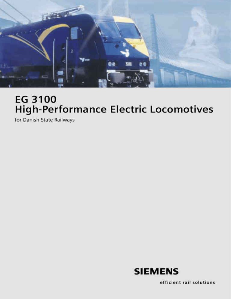
EG 3100 High-Performance Electric Locomotives for Danish State Railways s efficient rail solutions Six-axle titan Heavy-duty traffic between Germany, Denmark and Sweden Electrification of mainline railways did not begin in Denmark until after 1980. As there was no direct link with Sweden at that time, Danish State Railways (DSB) introduced a traction power system of their own, namely 25 kV 50 Hz. Since then, completion of the tunnel-and-bridge link over the A powerful family – EuroSprinter & Co. on the railways of the world Great Belt and the Øresund has created one continuous line between Germany, Denmark and Sweden. In Sweden, as in Germany, electric railways look back on a hundred year old tradition, but the Swedish railways still operate with the lower frequency of 16.7 Hz (= 1/3 of 50 Hz). Locomotives for cross-border traffic between Germany, Denmark and Sweden must therefore be equipped for both voltage systems. 2 Six axles for more adhesive weight High-performance for transit to the The EG 3100 aroused interest because To haul heavy freight trains with a trailing continent of its unusual livery, which is part of the load of up to 2,000 t through the Great In 1997, DSB ordered 13 dual-frequency new DSB corporate design. Belt tunnel with its 15.6 ‰ grades down locomotives from Siemens AG largely for to and up from the lowest level, the freight traffic between Sweden and the forms of the DB Cargo’s Class 152 loco- tractive effort of four-axle locomotives continent passing through Denmark. An motive. It was possible to take account is not enough. option for another seven exists. They are of DSB’s requirements with few alter- equipped with the Danish, Swedish and ations. The new Class EG 3100 therefore has six axles. Nevertheless it is derived from the modular concept of the EuroSprinter® The outer contour is based on the German train protection systems. With a high traction power of 6.5 MW family from Siemens Transportation and a starting tractive effort of 400 kN, Systems. Like the Class 152 already in the EG 3100 locomotive has been desig- service with the DB Cargo section of ned for the demands of cross-border Power systems German Rail, it is the second generation heavy freight traffic. Wheel arrangement Service weight Starting tractive effort Electrical braking effort maximum 240 kN Nominal power (continuous power) 6,500 kW Maximum speed 140 kph Gauge 1,435 mm Length over buffers 20,950 mm Mean distance of secondary suspension levels 10,200 mm Bogie wheelbase 2000/2250 mm Vehicle loading gauge (UIC 505-1) EBO G2 at roof level DSB gauge Temperature range -30°C to +40°C of the EuroSprinter. Modular structure The overall concept of the locomotive is based on a modular structure. Both the mechanical and electrical equipment is divided into pre-tested, ready-to-install modules. This has the advantage of reducing effort for maintenance and service work. Powerful design Technical data 25 kV/50 Hz 15 kV/16.7 Hz Co’Co’ 132 t 400 kN 3 Thorougly tested and computer-optimized The robust construction of the locomotive body The mechanical part of the EG 3100 was developed from the Class 152 locomotive, a unit characterized by its modular design. Strong backbone: Underframe placed upside down 4 Endurance test: Frame compression test to test the strength and deformation of the locomotive body Reinforced locomotive body Solid underframe The dimensions and the great weight of The welded underframe is formed by the six-axle locomotive made a series of two end sections under the driver’s cabs, adaptations necessary. For example, the two side sills and one center sill as well underframe has been made appropriately as a number of cross members. solid. The inclined lateral roof sections The side sills consist of 80-mm-thick have been strengthened with thicker steel plate. The cross members are bet- material and enclosed hollow sections to ween 20- and 50-mm-thick and form form longitudinal members so that they a hollow section with high torsional also make a considerable contribution rigidity with added strength provided to the rigidity of the locomotive body. by the 10-mm-thick floor plate. Robust structure: Driver’s cab section Because of the length of the locomotives, the cab door handrails had to be lowered to adhere to the loading gauge according to UIC 505-1. The locomotive body consists of the underframe, side walls with integrated inclined sections, three bolt-on cross members in the roof area and the two driver’s cabs. The roofs themselves are only mounted and are not bearing elements of the frame structure. Simple transmission of power The end sills of the frame, with the buffer and draw gear as well as the traction center pedestal for the draw and thrust rods for transmitting the tractive and braking effort, are welded on to the floor plates of the driver’s cabs to form hollow structures. This ensures a good and direct transmission of forces from the buffer and Good force transmission: Front section in the buffer area draw gear and tractive and braking effort transmission of the bogie to the side sills. Computer-optimized design The strength, deformation and vibration behavior of the locomotive body have been examined and optimized using powerful computer programs. Bearing structures: Solid end section of the frame 5 Ergonomic and comfortable Driver’s cab concept The driver’s ergonomically optimized workstation, as implemented in Class 152, is also used in DSB’s EG 3100. Here, too, an air-conditioning system is standard equipment. The heating power has been adapted to Scandinavian climatic conditions. Train radio operation Train protection systems Diagnostics equipment panel Brake equipment Traction and control equipment 6 Operation and monitoring of the locomo- The equipment with a pressurization tives have been made easier because the system permits energy-saving and con- operating and display concept is based stant temperature control of the internal both on the Danish EA 3000 locomotive temperature of the cab as well as pure class and on the German Class 152. recirculation without admitting outside All displays are in the driver’s field of vision and the controls within easy reach air. Pure recirculation prevents the ingress of the driver. Extendable exterior mirrors of exhaust gases or fumes especially in permit a visual check of the entire length tunnels and is not part of conventional of the train from the driver’s seat. A wash- ventilation and air-conditioning concepts. Open for fast installation: The front section before the driver’s console is installed basin and small thermal box are available in one of the cabs. A comfortable seat has been installed both for the driver and for the co-driver and can be adjusted to an optimum seating position with pneumatically assisted height and weight setting. 7 Strength and power on wheels Bogies Wear-free tractive effort Wear-free support and suspension transmission The bogie frame rests on the axle bear- The bogie frame consists of two longitu- ings via helical springs which also guide dinal members and cross members that the axles in the lateral direction. Hydraulic together form an enclosed frame. They dampers are arranged parallel with the are welded together from separate sheets springs on the first and last axle. to form box sections. Via the main cross members between the first and second and the fifth and axle runs with a higher natural play than sixth axles, the draw and thrust forces the outer axles to reduce the guidance are transmitted between the bogie and forces in curves, especially those of the the locomotive body. For that purpose, leading axle. the main cross members of the bogies are connected to the end sills of the locomotive frame by draw and thrust rods mounted in a wear-free arrangement. The low contact point of the forces ensures that, even during heavy starting, the load on all axles is the same for optimum tractive effort transmission. 8 In the bogie, the axles are mounted in cylindrical roller bearings. The center Wheelset guide links for longitudinal guidance overhead contact line. The air brakes act on all 12 wheels Each wheelset consist of two rolled solid via brake cylinders and brake calipers. – monobloc – wheels and a forged axle The associated brake disks are integrated shaft. Horizontally arranged wheelset into the monobloc wheels. Two brake guide links introduce the tractive forces units in each bogie are fitted with spring from the wheelsets into the bogie as accumulators. They can be used as a re- on Class 152, and provide longitudinal liable parking brake for the locomotive. guidance of the wheelsets in the track. Additional equipment Traction and braking The speed of each axle is sensed indivi- The three-phase asynchronous traction dually by contactless pulse encoders. motors are implemented as nose-suspen- The bogie is equipped with speed sensors ded motors. Like in the Class 152, they and antennas for the train protection rest on the axle shaft and are suspended equipment of the three countries. by a rubber-mounted torque reaction The bogies are also equipped with support on the next cross member of the neutral section control magnets for bogie. passing through phase sectioning points The two bogies with their three motors each form separate traction in the Danish railway network. For speed measurements indepen- groups. In that way, the locomotive can dent of the wheels, the locomotive can continue to run with reduced power if be retrofitted with radar measurement one group fails. equipment. The electrodynamic brake with reversal Driving force: Nose-suspension traction motor and nose-suspension bearing Well thought-out force transmission: Horizontal axle guides perform longitudinal guidance There are flange lubricators and of the energy flow permits regenerative sanders on the first and last axle of the feedback of the electrical energy into the locomotive. Closed frame: Solid box sections for the bogies 9 Compact, clearly arranged and maintenance-friendly Electrical components Machine compartment layout for easy All modules readily accessible maintenance Thanks to the underfloor arrangement of the main The two generously dimensioned driver’s cabs are transformer, the machine compartment layout connected by a wide center aisle of at least 600 remains uncluttered. All modules of the electrical mm that divides the machine compartment longitu- equipment as well as the racks for the compressed- dinally. The traction equipment for each bogie is air supply and for the auxiliaries are all equally arranged symmetrically on either side of the aisle readily accessible. for easy maintenance. Auxiliary inverters Traction motor blowers Air reservoir Auxiliary equipment rack Converters Oil-to-water cooler Electronics cabinet Air equipment rack Danish/Swedish ATC Filter rack 10 Transformer Traction converter The main transformer contains six traction Two independent converters initially windings and windings for the auxiliary convert the AC voltage output from the inverter, the heating units, the battery main transformer into a DC voltage. charger and the train supply bus. The PWMinverter generates three-phase When switching between the 15 and 25 kV systems, the disconnectors on the secondary side switch between the two taps. An additional transformer winding together with the filter components current from this with continuouslyregu- Dual-frequency traction voltage DS DS ES HS Q SA = M Q Q lated amplitude and frequency. SR 1~ = 1~ M Q Each converter consists of three four- Q quadrant choppers connected in parallel, Q one DC link and one inverter from which Q = 1~ M 3~ = the three traction motors of one bogie SR 1~ = M Q Q located in the machine compartment are powered and controlled separately form an interference current filter to for each bogie. The converters use Q reduce harmonics from the power sys- water-cooled GTO thyristors. Q = 1~ M Q = 1~ M = 3~ tem. Filter Q Q HBU 350 V Q Q 200 V Q Q DS HS ES Q SR M HBU ZSS SA ZSS Roof-mounted disconnector Main circuit breaker Grounding switch Disconnector for system switchover Converter Traction motor Auxiliary inverter Train supply bus Surge arrestor Three-phase current from AC voltage: Two converters feed three traction motors of a bogie 11 Auxiliaries The coolant pumps, all blowers and For the auxiliaries of the locomotive fans, and the air-conditioning equipment such as fans and pumps, the following are supplied from the on-board three- on-board power supply systems are phase power supply system. The on- available: board DC power supply system main- • Three-phase current with constant tains a number of functions even when frequency: 440 V/60 Hz the traction supply voltage is disconnect- • Three-phase current with continuously controllable frequency: 440 V/0 – 60 Hz ed. Especially when rigging up a locomotive whose paragraph is lowered, the • Alternating current 230 V/50 Hz required energy must be drawn from the • Direct current 110 V on-board lead-acid battery. This can be • Direct current 24 V charged by the charger powered from the 200 V winding of the main transformer or, if the traction supply voltage is disconnected, from a trackside power source. Control and protection systems Current, tailor-made: The auxiliary inverter For traction and brake control there Data exchange within the locomotive The traction and brake control as well as are also two units, but they are allocated is performed via a multifunction vehicle monitoring and diagnostic functions of to the two traction groups of each bogie. bus (MVB). All the main subsystems are the locomotive are performed exclusively If a traction control unit or brake connected via this vehicle bus. by microprocessor controllers. One main control unit fails, the bogie affected is feature of the control technology used in cut out and the locomotive remains matic wheel slip/slide control prevents the EG 3100 in this that it is equipped operable with reduced power. the axles from blocking during braking A microprocessor-controlled pneu- with two identical central control units and therefore avoids flats on the wheel (CCUs) that are 100 % redundant. running surfaces. TDM double-traction control via UIC line WTB-bus (optional) ATC system Driver’s cab 1 Driver’s cab 2 CCU 1 Recorder Aux. inv. 1.1 CCU 2 Aux. inv. 1.2 K-Micro Aux. inv. 2.1 Aux. inv. 2.2 MVB vehicle bus 1 SKS1 1 SKS1 Display lamp panel 4 3 TCU 1 SKS3 3 SKS3 SKS4 4 SKS4 BSG BCU TCU 2 Display lamp panel 2 2 SKS2 SKS2 12 Underfloor equipment means a neat arrangement: The main transformer is arranged under the machine compartment floor to save space above it Roof-mounted equipment Both pantographs on the roof of the locomotive are equipped with 1,950-mm-wide pans that are suitable for all three traction supply systems. The roof-mounted equipment also includes a disconnector for each pantograph, the main circuit breaker and the grounding disconnector. A surge arrester for protection against lightning strikes and a transducer for measuring the traction line voltage are also mounted on the roof. Cable routing The high-voltage cables to the traction motors and the train supply bus are located in a cable trough in the center sill. Other high-voltage cables are routed along the machine compartment floor under the racks. The signal and control lines and the supply lines to the auxiliaries are routed from cab to cab in a duct which is preassembled outside the locomotive. All pneumatic lines are located below this duct whose top cover forms the floor of the center aisle. No cable clutter: High-voltage cables are laid in a trough under the center aisle 13 Siemens AG Transportation Systems Locomotives Krauss-Maffei-Str. 2 80997 München Germany Siemens AG Transportation Systems Locomotives Postfach 3240 91050 Erlangen Germany www.siemens.com/ts Printed in Germany Subject to change without prior notice SAI 197-02 176619 PA 01031.0 Order No. A19100-V600-B432-V1-7600 The information in this document contains general descriptions of the technical options available, which do not always have to be present in individual cases.The required features should therefore be specified in each individual case at the time of closing the contract.
