HyperGrip Push/pull Quick Disconnect Plastic Connectors
advertisement

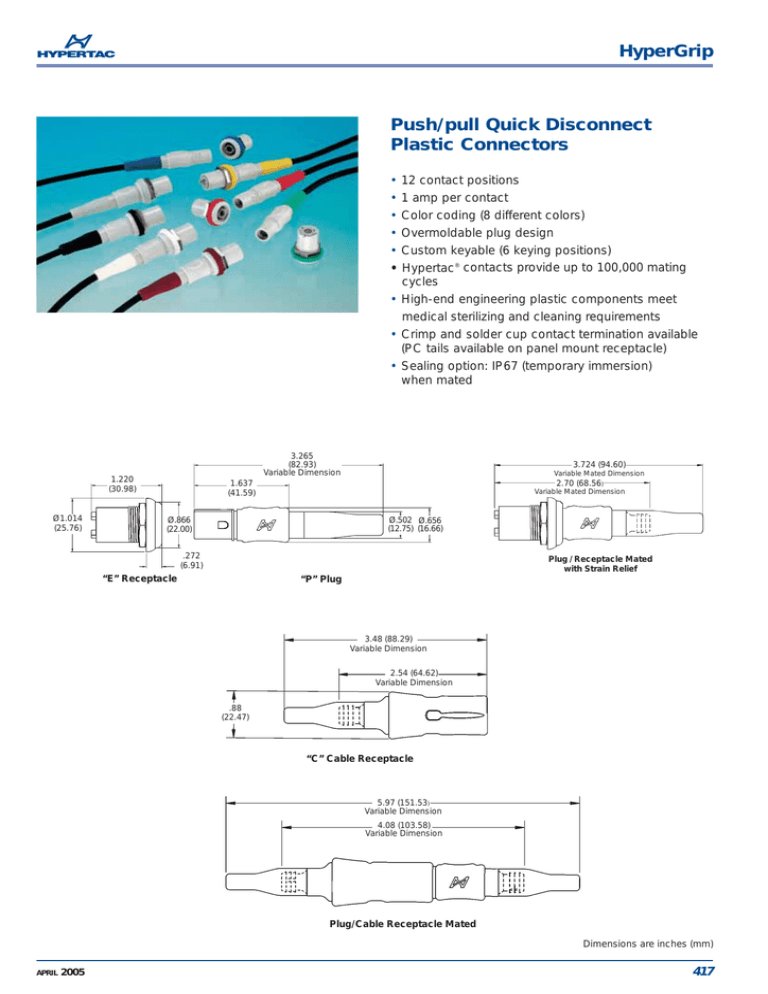
HyperGrip Push/pull Quick Disconnect Plastic Connectors • • • • • • 12 contact positions 1 amp per contact Color coding (8 different colors) Overmoldable plug design Custom keyable (6 keying positions) Hypertac® contacts provide up to 100,000 mating cycles • High-end engineering plastic components meet medical sterilizing and cleaning requirements • Crimp and solder cup contact termination available (PC tails available on panel mount receptacle) • Sealing option: IP67 (temporary immersion) when mated 3.265 (82.93) Variable Dimension 1.220 (30.98) Ø1.014 (25.76) 3.724 (94.60) Variable Mated Dimension 2.70 (68.56) 1.637 (41.59) Variable Mated Dimension Ø.866 (22.00) Ø.502 Ø.656 (12.75) (16.66) .272 (6.91) Plug / Receptacle Mated with Strain Relief “E” Receptacle “P” Plug 3.48 (88.29) Variable Dimension 2.54 (64.62) Variable Dimension .88 (22.47) “C” Cable Receptacle 5.97 (151.53) Variable Dimension 4.08 (103.58) Variable Dimension Plug/Cable Receptacle Mated Dimensions are inches (mm) APRIL 2005 417 HyperGrip HG2 General specifications - HG2 12 Pin Contact diameter in (mm) Current rating (amps) Contact resistance (milliohms) Contact extraction force each (oz.) Contact life cycles Plug cycle life Breakdown voltage between contacts Dielectric withstanding voltage Contact Material & Plating Insulation resistance Temperature Rating Polyetherimide, LCP, Silicone Sterilization .016 (0.4) 1 <8 .6 to 1.6 up to 100,000 up to 20,000 >1,000V >750V Ø.711 (18.05) .327 (8.31) Sockets: BeCu wires and brass body components 50 microinches of gold over nickel on wires Gold flash over nickel on all other socket components. Pins: Brass 50 microinches of gold over nickel >5 x 10⁴ MV @ 500 VDC -40°C to +105°C up to +185°C processing Steam autoclave, Gamma, ETO Panel Cutout Customer’s equipment Front Mounting Installation Customer’s harness or wiring Panel nut secures receptacle assembly from back Receptacle assembly with insulator installed and keyed to customer’s chosen keying position Customer’s equipment Rear Mounting Installation Customer’s harness or wiring Receptacle insulator with customer’s harness or wiring installed Receptacle case installed in customer’s equipment Dimensions are inches (mm) 418 APRIL 2005 HyperGrip HG2 12 Pin - Ordering Information HG 2 P 4 3 G G 12 04 M S H HyperGrip plastic circular Plating: H = 50 Microinch Gold on contact surfaces Gold flash on terminations AH = Sockets 50 Microinch Gold on contact surfaces Gold flash on terminations (omit for no contacts) Size: (2) Type: P = plug E = receptacle/panel C = receptacle/cable Termination: S = Solder cup R = Crimp D = Straight dip pc Panel receptacle only (omit for no contacts) Seal/Shield options: 1 = Sealed (unshielded) 2 = Shielded (unsealed) 3 = Sealed and shielded 4 = Unsealed (unshielded) Contact Gender: F = Female sockets (std receptacle) M = Male pins (std plug) N = No contacts Strain relief size options: 0 = No strain relief 3 = 3.0 - 4.5mm cable dia range 4 = 4.5 - 6.0mm cable dia range Outer shell color: G = LT gray Color coding: D = Blue B = Black G = LT Gray Y = Yellow M = Brown R = Red V = Green W = White N = No color code If “N” applies: Plug & Cable Receptacle- specify no strain relief (overmolding option) Panel Receptacle - Specify unsealed (no panel color code) Size HG2 Keying Position A (receptacle wiring end) Keying Position B (receptacle wiring end) Positions 12 Contact Diameter 0.4 mm Contact Ordering Information Contacts Part Numbers Wire Gauge (AWG) Notch A Keyed 3 4 C 2 12 5 10 6 C E D D 5 8 6 9 4 12 7 11 3 11 7 10 8 E B A 2 9 1 1 B Keyed F F Notch B A Note: 6 different keying positions possible - A through F Ø0.076 (1.94) Ø0.195 (4.95) 0.030 (12 x Ø0.76) 9 x 40 3 x 120 Female Receptacle Crimp Socket Solder Cup Socket PC Terminal Socket Male Plug Crimp Pin Solder Cup Pin Male Receptacle Crimp Pin Solder Cup Pin PC Terminal Pin Female Plug Crimp Socket Solder Cup Socket Tools Crimp Tool Positioner Insertion Tool YSK004-041AH YSK004-039AH YSK004-040AH 26 - 28 26 MAX N/A YPN004-028H YPN004-027H 26 - 28 26 MAX YPN004-029H YPN004-026H YPN004-030H 26 - 28 26 MAX N/A YSK004-037AH YSK004-036AH 26 - 28 26 MAX Part Numbers AFM8 or M22520/2-01 T2030 T1916 PCB Cutout (D Termination) Dimensions are inches (mm) APRIL 2005 419


