Be Careful When Making Voltage Measurements or Jumping
advertisement
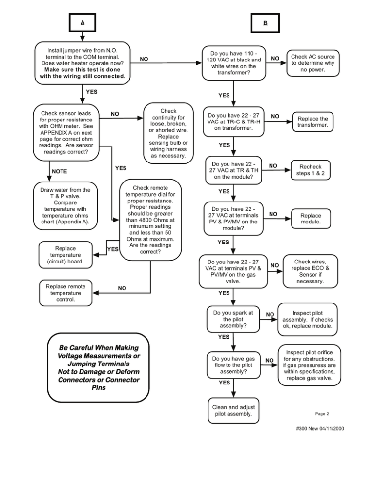
A B Install jumper wire from N.O. terminal to the COM terminal. Does water heater operate now? M ake sure this test is done with the wiring still connected. Do you have 110 120 VAC at black and white wires on the transformer? NO YES Check sensor leads for proper resistance with OHM meter. See APPENDIX A on next page for correct ohm readings. Are sensor readings correct? NOTE Replace remote temperature control. Check AC source to determine why no power. NO Replace the transformer. YES Check continuity for loose, broken, or shorted wire. Replace sensing bulb or wiring harness as necessary. NO YES Draw water from the T & P valve. Compare temperature with temperature ohms chart (Appendix A). Replace temperature (circuit) board. NO YES Check remote temperature dial for proper resistance. Proper readings should be greater than 4800 Ohms at minumum setting and less than 50 Ohms at maximum. Are the readings correct? Do you have 22 - 27 VAC at TR-C & TR-H on transformer. YES Do you have 22 27 VAC at TR & TH on the module? Recheck steps 1 & 2 NO Replace module. YES Do you have 22 27 VAC at terminals PV & PV/MV on the module? YES Do you have 22 - 27 VAC at terminals PV & PV/MV on the gas valve. NO NO NO Check wires, replace ECO & Sensor if necessary. YES Do you spark at the pilot assembly? NO Inspect pilot assembly. If checks ok, replace module. YES Be Careful When Making Voltage Measurements or Jumping Terminals Not to Damage or Deform Connectors or Connector Pins Do you have gas flow to the pilot assembly? YES Clean and adjust pilot assembly. NO Inspect pilot orifice for any obstructions. If gas pressuress are within specifications, replace gas valve. Page 2 #300 New 04/11/2000


