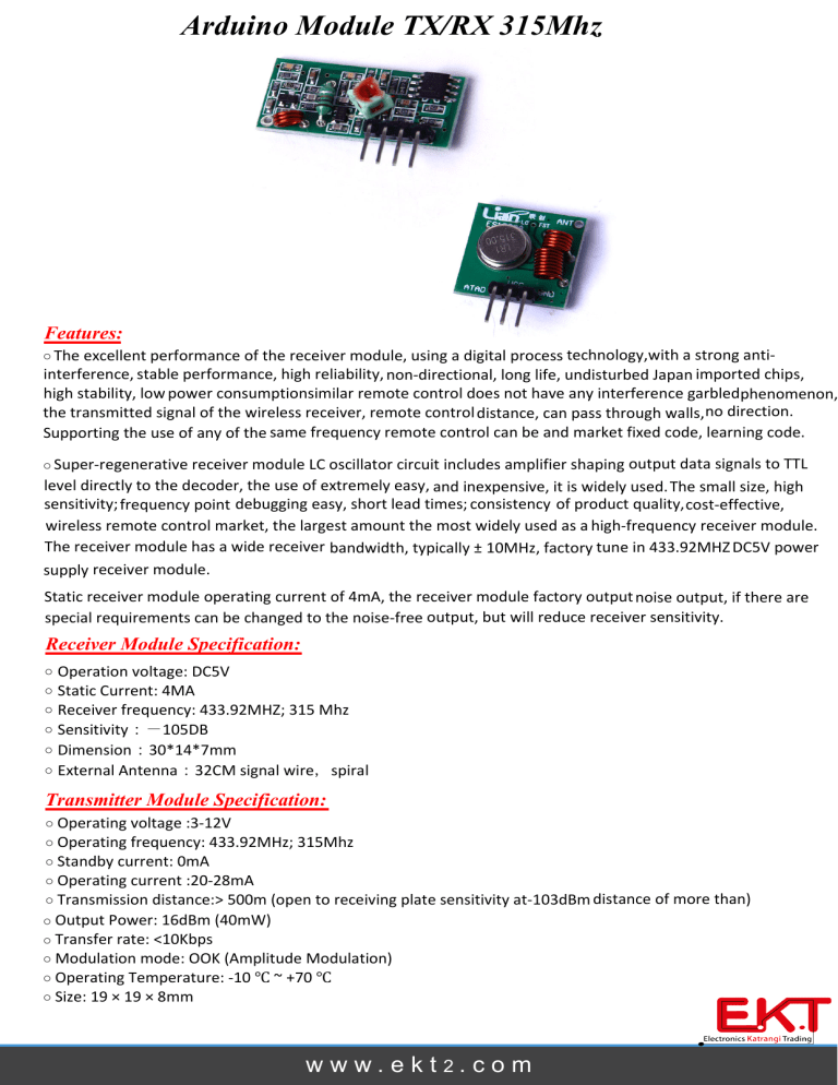
Arduino Module TX/RX 315Mhz

Arduino Module TX/RX 315Mhz
Features:
o
The excellent performance of the receiver module, using a digital process technology, with a strong anti ‐ interference, stable performance, high reliability, non ‐ directional, long life, undisturbed Japan imported chips,
high stability, low power consumptionsimilar remote control does not have any interference garbled phenomenon,
the transmitted signal of the wireless receiver, remote control distance, can pass through walls, no direction.
Supporting the use of any of the same frequency remote control can be and market fixed code, learning code.
o
Super ‐ regenerative receiver module LC oscillator circuit includes amplifier shaping output data signals to TTL level directly to the decoder, the use of extremely easy, and inexpensive, it is widely used.
The small size, high sensitivity; frequency point debugging easy, short lead times; consistency of product quality, cost ‐ effective, wireless remote control market, the largest amount the most widely used as a high ‐ frequency receiver module.
The receiver module has a wide receiver bandwidth, typically ± 10MHz, factory tune in 433.92MHZ
DC5V power supply receiver module.
Static receiver module operating current of 4mA, the receiver module factory output noise output, if there are special requirements can be changed to the noise ‐ free output, but will reduce receiver sensitivity.
Receiver Module Specification:
o
Operation voltage: DC5V o o o o o
Static Current: 4MA
Receiver frequency: 433.92MHZ; 315 Mhz
Sensitivity :- 105DB
Dimension : 30*14*7mm
External Antenna : 32CM signal wire , spiral
Transmitter Module Specification:
o o
Operating voltage :3 ‐ 12V
Operating frequency: 433.92MHz; 315Mhz o
Standby current: 0mA o
Operating current :20 ‐ 28mA o
Transmission distance:> 500m (open to receiving plate sensitivity at ‐ 103dBm distance of more than) o
Output Power: 16dBm (40mW) o
Transfer rate: <10Kbps o o
Modulation mode: OOK (Amplitude Modulation)
Operating Temperature: ‐ 10
Ԩ
~ +70
Ԩ
o
Size: 19 × 19 × 8mm
w w w . e k t 2 . c o m
This is a widely use module in many different application, the cost is very low and easy to use.
You have to use the
MCU to simulate decode and encode process as the IC PT 2262 and PT2272.
The popular link is like this:
MCU ‐ > Encoder ‐ > Transmitter —— Receiver ‐ > Decoder ‐ > MCU, PT2262(Encoder) and PT2272(Decoder) are optional, their existence is to 1)avoid confusing when multiple RF links in range 2) isolate disturbance.
You can integrate the encoding and decoding work to the MCUs on both side.
Whenever there is no 315Mhz devices around, you may use it as direct cable connection.
Excuse for the documentation, we will work on them.
We tried them using the guide from Sparkfun, it’s compatible.
Made in China
w w w . e k t 2 . c o m


