Technical Note TN CR 014, Frequently asked questions
TECHNICAL NOTE
TN CR 014
Frequently Asked Questions
Our utility supply is underground; do we need surge protection?
Having an underground supply reduces the chance of lightning transients from direct (galvanic) strikes to the line.
However, you are still at risk from all the other transient sources such as magnetically and capacitively induced lightning strikes, conducted transients generated by neighboring industry, switching of power factor correction equipment, utility substation switching and fault clearing on transmission lines. Therefore, yes, you do need surge protection.
How do SPDs work?
Surge Protection Devices (SPDs) are like pressure safety valves on a boiler, which release dangerous excess pressure from the system. SPDs are installed across the AC power supply in parallel with the equipment to be protected.
At normal operating voltages the SPDs are in a high impedance state and do not affect the system. When a transient voltage occurs on the supply, the SPD moves into a state of conduction (a low impedance) and diverts the transient energy/current back to its source or ground.
This limits (clamps) the voltage amplitude to a safer level.
After the transient is diverted the SPD will automatically reset back to its high impedance state.
What are the important SPD specifications for AC power protection?
After identifying the power distribution system to which the
SPD is to be connected, one should compare the following performance aspects of competing products:
1) Maximum Continuous Operating Voltage (MCOV) - aim for a figure of at least 25% above the nominal supply voltage.
2) Suppression Voltage - for 120V systems an SVR of
<400V for electronic equipment and <600V for electrical equipment is recommended. This may be provided by cascading two SPDs.
3) Surge Rating - approximately 100kA 8/20µs for service entrance and 40kA for branch circuits is recommended.
4) Indication Status - a progressive life status indication from 100% down to 0% in various stages is preferable to a simple Go/No-Go indicator.
It is recommended that customers ensure all specifications follow NEMA Standards Publication No. LS1 “Low Voltage
Surge Protective Devices”. This helps avoid specifications that may be written in a confusing or misleading manner.
Do I need to protect “all modes”?
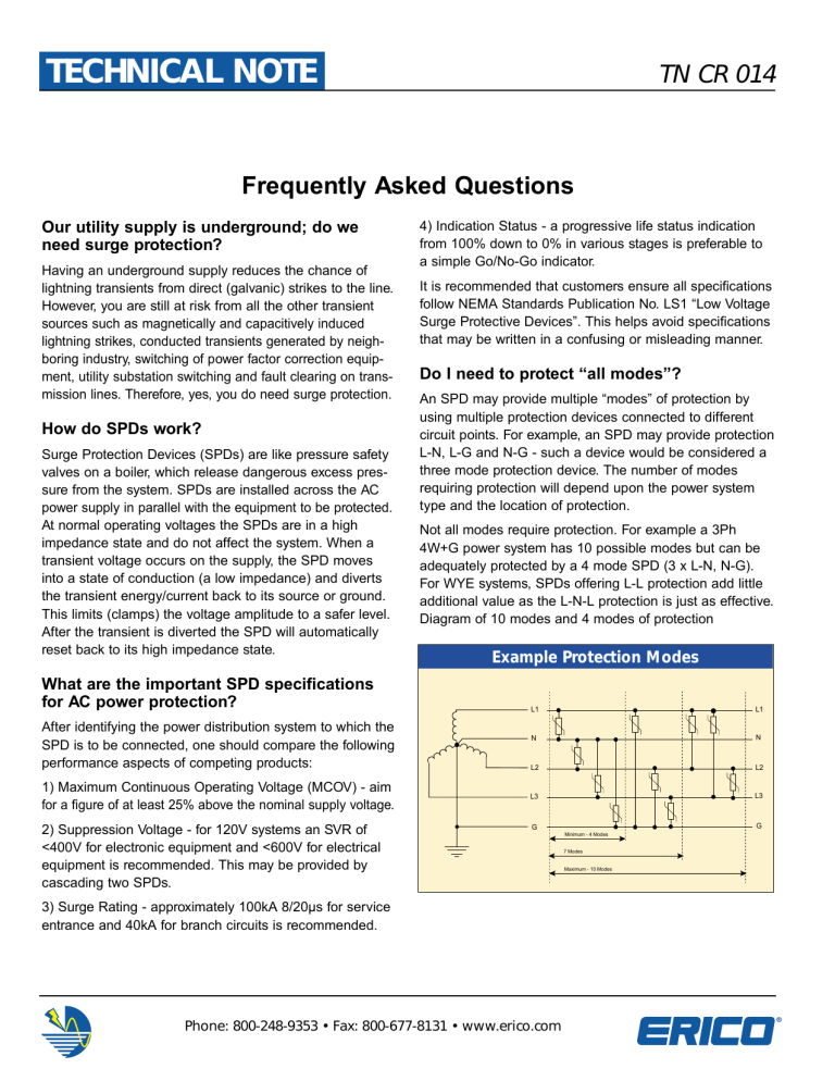
An SPD may provide multiple “modes” of protection by using multiple protection devices connected to different circuit points. For example, an SPD may provide protection
L-N, L-G and N-G - such a device would be considered a three mode protection device. The number of modes requiring protection will depend upon the power system type and the location of protection.
Not all modes require protection. For example a 3Ph
4W+G power system has 10 possible modes but can be adequately protected by a 4 mode SPD (3 x L-N, N-G).
For WYE systems, SPDs offering L-L protection add little additional value as the L-N-L protection is just as effective.
Diagram of 10 modes and 4 modes of protection
Example Protection Modes
L1
N
L2
L3
G
Minimum - 4 Modes
7 Modes
Maximum - 10 Modes
L1
N
L2
L3
G
Phone: 800-248-9353 • Fax: 800-677-8131 • www.erico.com
TN CR 014
(continued)
What speed of response is required?
Many manufacturers attempt to highlight the importance of response time of an SPD. While important, one must not lose sight of the fact that response time is not an end in itself. An SPD offering a fast response time generally implies that a lower clamping voltage will result, however this can not always be assumed. The equipment under protection is not affected by the SPD’s response time, but by the residual peak voltage and waveshape reaching it.
The magnitude of this residual voltage reaching the equipment is a result of many aspects of the SPD design including the surge & voltage ratings, the internal wire size, shape and loop area, the technology used and its speed of response. Of all these contributing factors, speed of response generally has the smallest influence. Standards bodies like UL, NEMA and IEEE advise that speed of response is not a valid specification for comparison of SPDs and that the let-through or clamping voltage should be used instead, because it includes speed of response and other more influential factors that affect an SPD’s ability to adequately protect downstream equipment.
Why do I need status indicators on my SPD?
Metal Oxide Varistors (MOVs) are ideally suited as voltage limiting devices due to their economical cost and effective surge capacities. They do, however exhibit an operational life which is proportional to the number and amplitude of the applied impulse. This life is non-linear, so doubling the surge rating provides a far greater length of life (typically
3-5 times) for the same size surge.
Most SPDs designed for service entrance or branch panel protection provide sufficient MOV material to give life expectations in excess of 10 years. Indication and alarm circuits should be provided by such devices to signal when their protection status has reduced to a level at which replacement maintenance is required. It is preferable that such indication occur prior to total depletion of the protection to allow a replacement module or device to be installed without the equipment being left unprotected.
What is Sinewave Tracking Filtering?
Sinewave Tracking and similar terms have more value as a marketing ploy than technical merit. Some will use a hybrid switching circuit to make this claim, while others will simply install a parallel capacitor. Sinewave filtering should not be confused with series Low Pass surge filtering, which is specifically designed to reduce the rate of voltage rise of the pre-clamped waveform. Refer to our Technical Note
TN CR 006 “SPDs and Filters” for further information.
What energy rating should I specify?
Surge protection devices must have sufficient energy ratings to withstand the expected impulses, however Joule ratings can be very misleading. Between two products, the one with the highest Joule rating may not be the one with the largest surge current rating. NEMA LS1 has determined that suppression voltage rating (SVR) and surge rating
(kA) specifications are a better way to compare products.
Do you have a question? Please review our internet site at www.erico.com. Should you not find the answer contact us by phone, fax or e-mail. We will be happy to address your specific questions.
Phone: 800-248-9353 • Fax: 800-677-8131 • www.erico.com

