The Piezoelectric Effect
advertisement

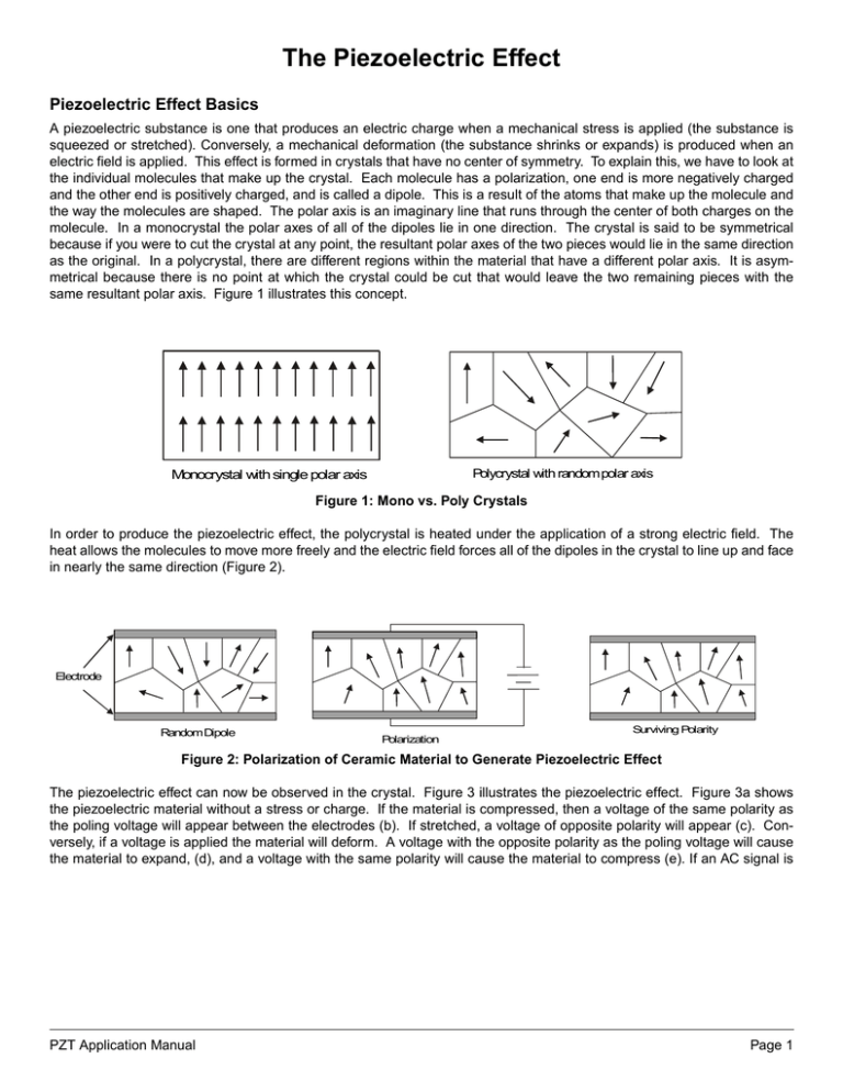
The Piezoelectric Effect Piezoelectric Effect Basics A piezoelectric substance is one that produces an electric charge when a mechanical stress is applied (the substance is squeezed or stretched). Conversely, a mechanical deformation (the substance shrinks or expands) is produced when an electric field is applied. This effect is formed in crystals that have no center of symmetry. To explain this, we have to look at the individual molecules that make up the crystal. Each molecule has a polarization, one end is more negatively charged and the other end is positively charged, and is called a dipole. This is a result of the atoms that make up the molecule and the way the molecules are shaped. The polar axis is an imaginary line that runs through the center of both charges on the molecule. In a monocrystal the polar axes of all of the dipoles lie in one direction. The crystal is said to be symmetrical because if you were to cut the crystal at any point, the resultant polar axes of the two pieces would lie in the same direction as the original. In a polycrystal, there are different regions within the material that have a different polar axis. It is asymmetrical because there is no point at which the crystal could be cut that would leave the two remaining pieces with the same resultant polar axis. Figure 1 illustrates this concept. Polycrystal with random polar axis Monocrystal with single polar axis Figure 1: Mono vs. Poly Crystals In order to produce the piezoelectric effect, the polycrystal is heated under the application of a strong electric field. The heat allows the molecules to move more freely and the electric field forces all of the dipoles in the crystal to line up and face in nearly the same direction (Figure 2). Electrode Random Dipole Surviving Polarity Polarization Figure 2: Polarization of Ceramic Material to Generate Piezoelectric Effect The piezoelectric effect can now be observed in the crystal. Figure 3 illustrates the piezoelectric effect. Figure 3a shows the piezoelectric material without a stress or charge. If the material is compressed, then a voltage of the same polarity as the poling voltage will appear between the electrodes (b). If stretched, a voltage of opposite polarity will appear (c). Conversely, if a voltage is applied the material will deform. A voltage with the opposite polarity as the poling voltage will cause the material to expand, (d), and a voltage with the same polarity will cause the material to compress (e). If an AC signal is PZT Application Manual Page 1 applied then the material will vibrate at the same frequency as the signal (f). - Poling Axis - + + + + - + (c) (b) (a) + + + (d) - + (e) (f) Figure 3: Example of Piezoelectric Effect Using the Piezoelectric Effect The piezoelectric crystal bends in different ways at different frequencies. This bending is called the vibration mode. The crystal can be made into various shapes to achieve different vibration modes. To realize small, cost effective, and high performance products, several modes have been developed to operate over several frequency ranges. These modes allow us to make products working in the low kHz range up to the MHz range. Figure 4 shows the vibration modes and the frequencies over which they can work. An important group of piezoelectric materials are ceramics. Murata utilizes these various vibration modes and ceramics to make many useful products, such as ceramic resonators, ceramic bandpass filters, ceramic discriminators, ceramic traps, SAW filters, and buzzers. Page 2 PZT Application Manual Vibration Mode Flexure Vibration Frequency (Hz) 1K 10K 100K 1M 10M 100M 1G Application Piezo Buzzer Lengthwise Vibration Area Vibration KHz Filter KHz Resonator Radius Vibration Thickness Shear Vibration MHz Filter Thickness Trapped Vibration MHz Resonator Surface Acoustic Wave SAW Filter SAW Resonator BGS Wave SH Trap SH Resonator SH Filter Figure 4: Various Vibration Modes Possible with Piezoelectric Ceramics PZT Application Manual Page 3


