Fleetwood Motorhome Slideout Systems Operations Manual
advertisement

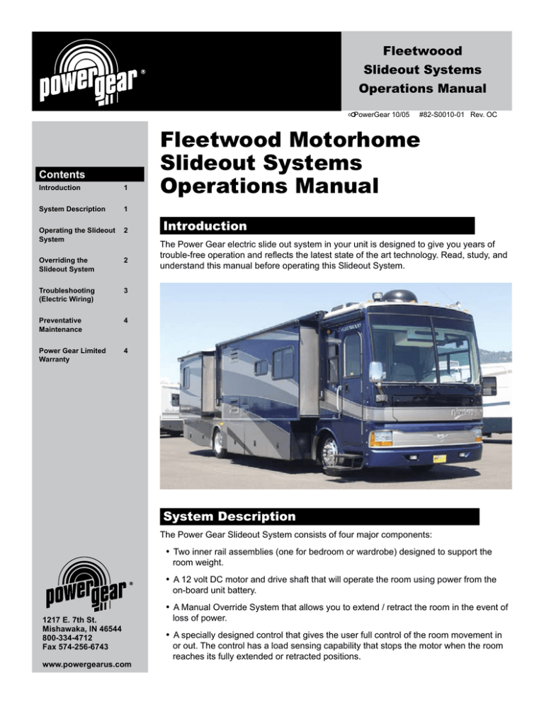
Fleetwoood Page Slideout Systems Operations Manual c Contents Introduction 1 System Description 1 Operating the Slideout System 2 Overriding the Slideout System 2 Troubleshooting (Electric Wiring) 3 Preventative Maintenance 4 Power Gear Limited Warranty 4 PowerGear 10/05 #82-S0010-01 Rev. OC Fleetwood Motorhome Slideout Systems Operations Manual Introduction The Power Gear electric slide out system in your unit is designed to give you years of trouble-free operation and reflects the latest state of the art technology. Read, study, and understand this manual before operating this Slideout System. System Description The Power Gear Slideout System consists of four major components: n n n 1217 E. 7th St. Mishawaka, IN 46544 800-334-4712 Fax 574-256-6743 www.powergearus.com n Two inner rail assemblies (one for bedroom or wardrobe) designed to support the room weight. A 12 volt DC motor and drive shaft that will operate the room using power from the on-board unit battery. A Manual Override System that allows you to extend / retract the room in the event of loss of power. A specially designed control that gives the user full control of the room movement in or out. The control has a load sensing capability that stops the motor when the room reaches its fully extended or retracted positions. Page Operating the Slideout System » Always make sure that the unit is level before operating the Slideout room. » Always make sure there are no obstructions blocking the path of the room when it is moving. » Always make sure that the room path is clear of people and objects before operating. » Always keep away from the slide rails when the room is in motion. The gear assembly may pinch or catch on loose clothing causing person injury. » Failure to follow these instructions could result in serious injury or death. Before you operate the Power Gear Slideout System, make sure: Slide-Out RoomControl 1.The path is clear for the room to move. OUTIN 2.The battery is fully charged and hookedup to the unit’s electrical system. WARNING! 3. The unit is level. Extending the Room 1.Insert the Switch Key into the Slideout Room Control. 2.Turn the Switch Key to the OUT position. 3. Hold the Switch in the OUT position until the room is fully extended and stops moving. The control will sense that the room has stopped and will automatically shut off the motor, locking the room into place. Keeppeopleclearofroomwhen inoperation.Makesureareais clearofobstacles. Retracting the Room 1.Insert the Switch Key into the Slideout Room Control 2.Turn the Switch Key to the IN position. 3. Hold the Switch in the IN position until the room is fully retracted and stops moving. The Control will sense that the room has stopped and will automatically shut off the motor, locking the room into place. 4. Release the Switch Key. 4. Release the Switch Key. 5.The Key may now be removed from the Switch if necessary. 5.The Key may now be removed from the Switch if necessary. Overriding the Slideout System Your Power Gear Slideout System is equipped with a manual override that allows you to extend or retract a room in the event of a loss of power. If your system will not move when the Switch is pressed, make sure that the system is turned on and the battery is connected and has a full charge. After all of these are completed, follow these simple steps to move the room manually. Main Room Slideout 1.Make sure that the ON/OFF Switch Key for the system is turned off. 2.Locate the Slideout Motor. It will be either ahead of the front rail or behind the back rail. 3.Locate the two-pin connector on the Slideout Motor leads and disconnect. 4.Rotate the lever on the backside of the motor counter-clockwise about 1/8th turn (looking from the rear of the motor). This will release the break that holds the room in place. 5.The room is now free to move. Using a 3/4th wrench or rachet, crank the room either in or out (depending on your need) using the manual override. 6. When the room is fully in or out, have one person put pressure on the wrench/ rachet to ensure a tight seal while the another person returns the Brake Lever to its normal downward locked travel position. This will ensure that the room is locked into a sealed position. 7.Take the unit to an authorized dealer for service. Page FleetwoodSlideouts » When the Slideout room Motor Brake Lever is released, the room will not lock into place and therefore not be sealed from the outside elements. Outerrail (welded inframe) » When the room has been cranked in, be sure to return the Motor Brake Lever to its normal downward position in order to seal and lock the room. Motor 1.Make sure that the ON/OFF Switch Key for the system is turned off. Black 2.Locate the Slideout mechanism. To access the bedroom Slideout, lift up the mattress and baseboard. To access the wardrobe Slideout, open the outside luggage compartment below the wardrobe. MotorBrake Engage Release Red Warning:BrakeMustBe EngagedPriortoTransit PowerGear Mishawaka,IN48544 Pat.No.5,833,296 Pat.No.5,833,296 Innerrail assembly RoomSlide Motor Manual override Driveshaft Innerrail Bedframe Manual override NOTE:WardrobeSlideis similartoBedroomSlide Bedroom / Wardrobe Slideout BrakeRelease P/N: S/N: Bedroom Slide 3.Locate the two-pin connector on the Slideout Motor leads and disconnect. 4.The bedroom Slideout Motor has a lever on the backside. Rotate the lever counter-clockwise about 1/8th turn (looking from the rear of the motor). This will release the break that holds the room in place. P/N: S/N: PowerGear Mishawaka,IN48544 Pat.No.5,833,296 5.The room is now free to move. Using a 3/4th wrench/rachet or adjustable wrench, crank the room either in or out (depending on your need) using the manual override. The manual override is located on the opposite side of the Slideout rail from the Motor. 6.When the room is fully in or out, put pressure on the wrench/rachet to ensure a tight seal and return` the Brake Lever to its normal downward locked travel position. This will ensure that the room is locked into a sealed position. 7.Take the unit to an authorized dealer for service. Pat.No.5,833,296 Brake End Troubleshooting Electrical Wiring Information Wiring Auto-Reset CurcuitBreaker SlideRoomControl INOFFOUT MotorMotorSwitchSwitch 12VGround 12INOUT WARNING! Setparkingbrakeandlevelvehicle beforeoperting.Pleasereadand understandyourownersmanual. 1 2 3 SlideRoomControl Black Red ToParking BrakeSignal + » NOTE: If the motor runs in the reverse direction, switch motor leads. -- 12VoltBattery Motor The wiring for the Slideout should be completed per the following diagram. The switch wires, motor wires and ground wire can be connected to the control at any time during installation prior to the power being connected. The battery line must be connected BEFORE the battery is connected. WireSpecifications 10AWG 16AWG » The Control Box WILL be damaged if any of the leads are grounded or touched together when power is connected to the system. Page Preventative Maintenance » Do not work on your system unless the battery is disconnected. Your Power Gear Slideout system has been designed to require very little maintenance. To ensure the long life of your Slideout system, read and follow these few simple procedures: n When the room is out, visually inspect the inner slide rail assemblies. Check for excess buildup of dirt of foreign material. Remove any debris that may be present. n If the system squeaks or makes any noises, it is permissible to apply a coat of light weight oil to the drive shaft and roller areas. Remove any excess oil so dirt and debris do not build up. If you have any problems or questions consult your local authorized dealer or call us at Power Gear, 1-800-334-4712. Power Gear Limited Warranty Power Gear warrants to the original retail purchaser that the product will be free from defects in material and workmanship for a period of two (2) years following the retail sales date. Power Gear will, at its option, repair or replace any part covered by this limited warranty which, following examination by Power Gear or its authorized distributors or dealers, is found to be defective under normal use and service. No claims under this warranty will be valid unless Power Gear or its authorized distributor or dealer is notified in writing of such a claim prior to the expiration of the warranty period. This Warranty shall not apply to: n n n n 1217 E. 7th St. Mishawaka, IN 46544 800-334-4712 Fax 574-256-6743 www.powergearus.com n n Failure due to normal wear and tear, accident, misuse, abuse, or negligence. Products which are modified or latered in a manner not authorized by Power Gear in writing. Failure due to misapplication of product. Telephone, telegraph, teletype or other communication expenses. Living or travel expenses of person performing service. Overtime labor. n n Failures created by improper installation of the product’s Slideout systems, including final adjustments made at the plant, or low fluid level, wiring or ground problems. Replacement of normal maintenance items including lubricants and fuses. There is no other express warranty other than the foregoing warranty. There are no implied warranties of merchantability or fitness for a particular purpose. In no event shall Power Gear be liable for any incidental or consequential damages. This warranty gives you specific legal rights, and you may also have other rights, which vary from state to state. Some states do not allow the limitations of implied warranties, or the exclusion of incidential damages, so the above limitations and exclusions may not apply to you. For service, contact your nearest PowerGear authorized warranty facility or call 1-800-334-4712. Warranty service can be performed only by a Power Gear authorized warranty facility. This warranty will not apply to service at any other facility. At the time of requesting warranty service, evidence of original purchase date must be presented.


