on–vehicle inspection (4a–fe)
advertisement

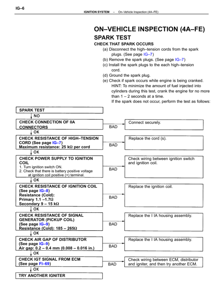
IG–6 IGNITION SYSTEM – On–Vehicle Inspection (4A–FE) ON–VEHICLE INSPECTION (4A–FE) SPARK TEST CHECK THAT SPARK OCCURS (a) Disconnect the high–tension cords from the spark plugs. (See page IG–7) (b) Remove the spark plugs. (See page IG–7) (c) Install the spark plugs to the each high–tension cord. (d) Ground the spark plug. (e) Check if spark occurs while engine is being cranked. HINT: To minimize the amount of fuel injected into cylinders during this test, crank the engine for no more than 1 – 2 seconds at a time. If the spark does not occur, perform the test as follows: SPARK TEST CHECK CONNECTION OF IIA CONNECTORS CHECK RESISTANCE OF HIGH–TENSION CORD (See page IG–7) Maximum resistance: 25 k per cord Connect securely. BAD Replace the cord (s). BAD CHECK POWER SUPPLY TO IGNITION COIL 1. Turn ignition switch ON. 2. Check that there is battery positive voltage at ignition coil positive (+) terminal. CHECK RESISTANCE OF IGNITION COIL (See page IG–8) Resistance (Cold): Primary 1.1 –1.7 Secondary 9 – 15 k CHECK RESISTANCE OF SIGNAL GENERATOR (PICKUP COIL) (See page IG–9) Resistance (Cold): 185 – 265 CHECK AIR GAP OF DISTRIBUTOR (See page IG–9) Air gap: 0.2 – 0.4 mm (0.008 – 0.016 in.) CHECK IGT SIGNAL FROM ECM (See page FI–69) TRY ANOTHER IGNITER Check wiring between ignition switch and ignition coil. BAD Replace the ignition coil. BAD Replace the I IA housing assembly. BAD Replace the I IA housing assembly. BAD BAD Check wiring between ECM, distributor and igniter, and then try another ECM. IG–7 IGNITION SYSTEM – On–Vehicle Inspection (4A–FE) INSPECTION OF HIGH–TENSION CORDS 1. DISCONNECT HIGH–TENSION CORDS FROM SPARK PLUGS Disconnect the high–tension cords at the rubber boot. DO NOT pull on the cords. NOTICE: Pulling on or bending the cords may damage the conductor inside. 2. REMOVE IIA CAP WITHOUT DISCONNECTING HIGH–TENSION CORDS 3. INSPECT HIGH–TENSION CORD RESISTANCE Using an ohmmeter: measure the resistance without dis– connecting the IIA cap. Maximum resistance: 25 k per cord If the resistance is greater than maximum, check the ter– minals. If necessary, replace the high–tension cord and/ or IIA cap. 4. REINSTALL IIA CAP 5. RECONNECT HIGH–TENSION CORDS TO SPARK PLUGS INSPECTION OF SPARK PLUGS 1. DISCONNECT HIGH–TENSION CORDS FROM SPARK PLUGS 2. REMOVE SPARK PLUGS Using a 16 mm plug wrench, remove the spark plug. 3. CLEAN SPARK PLUGS Using spark plug cleaner or wire brush, clean the spark plug. 4. VISUALLY INSPECT SPARK PLUGS Check the spark plug for electrode wear, thread damage and insulator damage. If abnormal, replace the spark plug. Recommended spark plug: ND Q16R–U NGK BCPR5EY IG–8 IGNITION SYSTEM – On–Vehicle Inspection (4A–FE) 5. ADJUST ELECTRODE CAP Carefully bend the outer electrode to obtain the correct electrode gap. Correct electrode gap: 0.8 mm (0.31 in.) 6. INSTALL SPARK PLUGS Using a 16 mm plug wrench, install the spark plug. Torque: 18 N–m (180 kgf–cm,13 ft–Ibf) 7. RECONNECT HIGH–TENSION CORDS TO SPARK PLUGS INSPECTION OF IIA 1. 2. 3. 4. DISCONNECT IIA CONNECTORS REMOVE IIA CAP REMOVE DISTRIBUTOR ROTOR REMOVE IGNITION COIL AND IGNITER DUST COVERS Ignition Coil 5. INSPECT PRIMARY COIL RESISTANCE Using an ohmmeter, measure the resistance between positive ( + ) and negative (–) terminals. Primary coil resistance (Cold): 1.1 ~ 1.7 at –10 ~ +400C (14 ~ 1040F) If the resistance is not as specified, replace the ignition coil. 6. INSPECT SECONDARY COIL RESISTANCE Using an ohmmeter, measure the resistance between the positive ( + ) and high–tension terminals. Secondary coil resistance (Cold): 9 ~ 15 k at –10 ~ +400C (14 ~ 104F) If the resistance is not as specified, replace the ignition coil. IG–9 IGNITION SYSTEM – On–Vehicle Inspection (4A–FE) Distributor 7. INSPECT AIR GAP Using a thickness gauge, measure the gap between the signal rotor and pickup coil projection. Air gap: 0.2 – 0.4 mm (0.008 – 0.016 in.) If the air gap is not as specified, replace the IIA housing assembly. 8. INSPECT SIGNAL GENERATOR (PICKUP COIL) RESISTANCE Using an ohmmeter, measure the resistance between the terminals (G1 and GE(–), NE and G(–)). Pickup coil resistance (Cold): 185 – 265 92 at –10 – +400C (14 – 1040F) If the resistance is not as specified, replace the IIA housing assembly. 9. REINSTALL IGNITION COIL AND IGNITER DUST COVERS 10. REINSTALL DISTRIBUTOR ROTOR 11. REINSTALL IIA CAP 12. RECONNECT IIA CONNECTORS Igniter (See procedure Spark Test on page IG–6)


