1 According to Lenz`s Law the direction of the induced current
advertisement
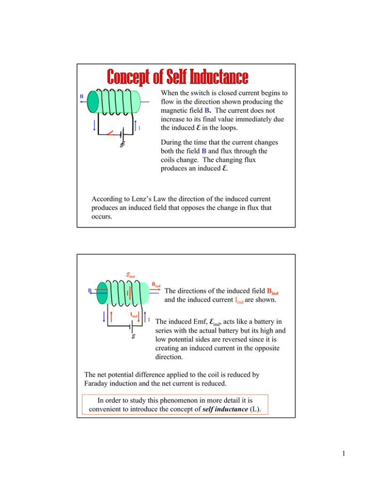
When the switch is closed current begins to flow in the direction shown producing the magnetic field B. The current does not increase to its final value immediately due the induced E in the loops. B I During the time that the current changes both the field B and flux through the coils change. The changing flux produces an induced E. EE According to Lenz’s Law the direction of the induced current produces an induced field that opposes the change in flux that occurs. Eind Bind B Iind E I The directions of the induced field Bind and the induced current Iind are shown. The induced Emf, Eind, acts like a battery in series with the actual battery but its high and low potential sides are reversed since it is creating an induced current in the opposite direction. The net potential difference applied to the coil is reduced by Faraday induction and the net current is reduced. In order to study this phenomenon in more detail it is convenient to introduce the concept of self inductance (L). 1 Self Inductance B Φ - magnetic flux through one loop Φtotal - total flux through all loops N loops Φtotal = NΦ I E The flux depends directly on B which in turn depends directly on the current in the coils. Φ total ∝ I ⇒ N Φ = LI NΦ The proportionality constant (L) is called the “self inductance” L= and depends on the geometry of the coils. Its value is found from: I LI E =− The induced E is: dΦ total d ( NΦ ) dI =− = −L dt dt dt Units for inductance: Henry (H). l B Self Inductance of a Long Coil A N loops I From Ampere’s law the field inside the coil is: µ NI B= Φ = BA cos 0 = The flux through one coil is: The self inductance is: L= 0 l µ 0 NAI l NΦ µ 0 N 2 AI µ 0 N 2 A = = I Il l 2


