Â
advertisement
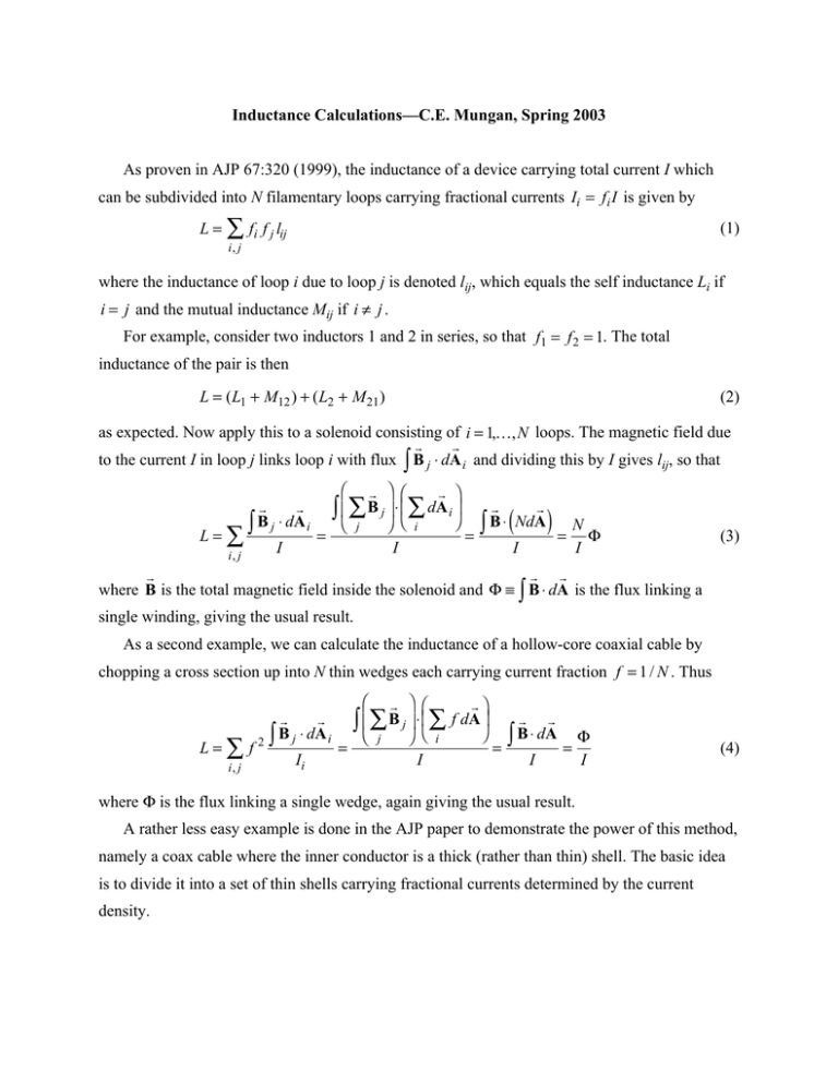
Inductance Calculations—C.E. Mungan, Spring 2003 As proven in AJP 67:320 (1999), the inductance of a device carrying total current I which can be subdivided into N filamentary loops carrying fractional currents Ii = fi I is given by L =  fi f j lij (1) i, j where the inductance of loop i due to loop j is denoted lij, which equals the self inductance Li if i = j and the mutual inductance Mij if i π j . For example, consider two inductors 1 and 2 in series, so that f1 = f 2 = 1. The total inductance of the pair is then L = ( L1 + M12 ) + ( L2 + M 21 ) (2) as expected. Now apply this to a solenoid consisting of i = 1,K, N loops. The magnetic field due r r to the current I in loop j links loop i with flux Ú B j ◊ dA i and dividing this by I gives lij, so that L= r r ◊ d B A Ú j i i, j I Ê r ˆ Ê r ˆ ◊ d B A Á Ú Á  j ˜ Ë Â i ˜¯ Br ◊ NdAr ¯ i Ë j N Ú = = = F I I I ( ) (3) r r r where B is the total magnetic field inside the solenoid and F ∫ Ú B ◊ dA is the flux linking a single winding, giving the usual result. As a second example, we can calculate the inductance of a hollow-core coaxial cable by chopping a cross section up into N thin wedges each carrying current fraction f = 1 / N . Thus L=Âf i, j r r ◊ d B A j i 2Ú Ii Ê r ˆ Ê rˆ ◊ f d B A Á Ú Á  j ˜ Ë Â ˜¯ Br ◊ dAr ¯ i Ë j F Ú = = = I I I (4) where F is the flux linking a single wedge, again giving the usual result. A rather less easy example is done in the AJP paper to demonstrate the power of this method, namely a coax cable where the inner conductor is a thick (rather than thin) shell. The basic idea is to divide it into a set of thin shells carrying fractional currents determined by the current density.
