Chapter 3.1 Meter Movements
advertisement

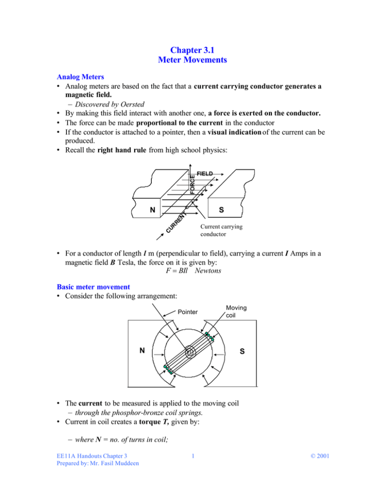
Chapter 3.1 Meter Movements FORCE Analog Meters • Analog meters are based on the fact that a current carrying conductor generates a magnetic field. – Discovered by Oersted • By making this field interact with another one, a force is exerted on the conductor. • The force can be made proportional to the current in the conductor • If the conductor is attached to a pointer, then a visual indication of the current can be produced. • Recall the right hand rule from high school physics: FIELD S CU RR EN T N Current carrying conductor • For a conductor of length l m (perpendicular to field), carrying a current I Amps in a magnetic field B Tesla, the force on it is given by: F = BIl Newtons Basic meter movement • Consider the following arrangement: Pointer Moving coil N S • The current to be measured is applied to the moving coil – through the phosphor-bronze coil springs. • Current in coil creates a torque T, given by: – where N = no. of turns in coil; T = BNIA sin α EE11A Handouts Chapter 3 Prepared by: Mr. Fasil Muddeen 1 © 2001 – I = current – A = CSA of coil – α = angle between the normal plane of the coil and the field. • • • • B, N and A are constant By appropriately shaping the pole pieces, α is kept constant Therefore T∝ I T causes rotation of coil which is opposed by the tension in the coil spring until a balance is obtained. • If we project the pointer movement onto a scale, we can obtain a direct indication of the current reading. • When current is removed, coil spring tension causes pointer to return to zero. • Is the pointer movement linear or nonlinear? • This type of meter mechanism or meter movement is called the D’Arsonval movement or the Permanent Magnet Moving Coil (PMMC) movement • Know both terms! • Figure 4-3 pg 86 in the text shows the main features of a PMMC meter movement Sensitivity of PMMC movement • Recall our definition of sensitivity – A measure of how much of an input is required to produce a specific output. Sensitivity = Incremental Change in Output Incrementa l Change in Input • In the case of analog meters the sensitivity is the amount of current required to give a FSD • Since T = BNIAsinα α , to maximise T; either increase N or A. Either choice means more weight and more wire resistance and therefore a compromise has to be reached between weight, resistance and sensitivity. • Typical PMMC movement sensitivities and the associated coil resistances are given in the following table. IFSD Resistance 50µ µA 1000-5000 Ω 500µA 100-1000 Ω 1mA 30-120 Ω 10mA 1-4 Ω • Therefore as sensitivity increases so too does the coil resistance. EE11A Handouts Chapter 3 Prepared by: Mr. Fasil Muddeen 2 © 2001


