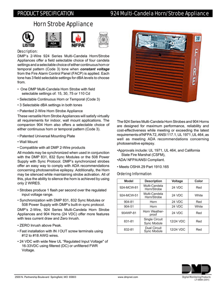
Horn Strobe Appliance
advertisement

PRODUCT SPECIFICATION 924 Multi-Candela Horn/Strobe Appliance ACTION MESSAGES ADA SYSTEMS COMMUNICATIONS Horn Strobe Appliance Description: DMP’s 2-Wire 924 Series Multi-Candela Horn/Strobe Appliances offer a field selectable choice of four candela settings and a selectable choice of either continuous horn or temporal pattern (Code 3) tone when constant voltage from the Fire Alarm Control Panel (FACP) is applied. Each tone has 3 field selectable settings for dBA levels to choose from. • One DMP Multi-Candela Horn Strobe with field selectable settings of: 15, 30, 75 or 110 Cd • Selectable Continuous Horn or Temporal (Code 3) • 3 Selectable dBA settings in both tones • Patented 2-Wire Horn Strobe Appliance These versatile Horn Strobe Appliances will satisfy virtually all requirements for indoor, wall mount applications. The companion 904 Horn also offers a selectable choice of either continuous horn or temporal pattern (Code 3). • Patented Universal Mounting Plate • Wall Mount • Compatible with all DMP 2-Wire products All models may be synchronized when used in conjunction with the DMP 831, 832 Sync Modules or the 508 Power Supply with Sync Protocol. DMP’s synchronized strobes offer an easy way to comply with ADA recommendations concerning photosensitive epilepsy. Additionally, the Horn may be silenced while maintaining strobe activation. All of this, plus the ability to silence the horn is achieved by using only 2 WIRES. • Strobes produce 1 flash per second over the regulated input voltage range. • Synchronization with DMP 831, 832 Sync Modules or 508 Power Supply with DMP’s built-in sync protocol. DMP’s 2-Wire, 924 Series Multi-Candela Horn Strobe Appliances and 904 Horns (24 VDC) offer more features with less current draw and Zero Inrush. The 924 Series Multi-Candela Horn Strobes and 904 Horns are designed for maximum performance, reliability and cost-effectiveness while meeting or exceeding the latest requirements of NFPA 72, ANSI 117.1, UL 1971 ,UL 464, as well as meeting ADA recommendations concerning photosensitive epilepsy. •Approvals include: UL 1971, UL 464, and California State Fire Marshal (CSFM), •ADA/ NFPA/ANSI Compliant. • Meets OSHA 29 Part 1910.165 Ordering Information Model 924-MCW-81 924-MCW-51 904-81 904-51 904WP-81 831-81 • ZERO Inrush above Peak. • Fast installation with IN I OUT screw terminals using #12 to #18 AWG wires. 832-81 Description Multi-Candela Horn/Strobe Multi-Candela Horn/Strobe Horn Horn Horn Weatherproof Single Circuit Sync Module Dual Circuit Sync Module Voltage Color 24 VDC Red 24 VDC White 24 VDC 24 VDC Red White 24 VDC Red 12/24 VDC Red 12/24 VDC Red • 24 VDC with wide New UL “Regulated Input Voltage" of 16-33VDC using filtered (DC) or unfiltered FWR Voltage. 2500 N. Partnership Boulevard Springfield, MO 65803 www.dmpnet.com Digital Monitoring Products LT-0559 (3/01) Mounting Options Specifications DMP Model 841, Option H, NATP DMP Model 842, Option X, SHBB surface backbox DMP Model 845, Option K, WBB backbox (904 Horn) DMP Model 846, Option J, BB backbox Option B - Single gang, flush Option D, 4" square, flush Option E, 4" square, deep flush Option F, double gang, flush Option G, double gang, surface Option O, RP-R retrofit plate Options R, SFP semi-flush plate Option S, AP adapter plate Refer to LT-0459 Fire Notification Mounting Accessories Warning: Please read these specifications and associated installation instructions carefully before using, specifying or applying this product. Failure to comply with any of these instructions, cautions and warnings could result in improper application, installation and/or operation of these products in an emergency situation, which could result in property damage, and serious injury or death to you and/or others. General Notes: • Strobes are designed to flash at 1 flash per second minimum over the “Regulated Input Voltage Range" of 1633 VDC (for 24 VDC models). Note that NFPA-72 (1999) specifies a flash rate of 1 to 2 flashes per second and ADA Guidelines specify a flash rate of 1 to 3 flashes per second. • All candela ratings represent minimum effective Strobe intensity based on UL 1971. • 924 Series Multi-Candela Strobe products are listed under UL 1971 for indoor use with a temperature range of 320F to 1200F (00C to 490C) and maximum humidity of 85%. “Regulated Input Voltage Range" is the newest terminology used by UL to identify the voltage range. Prior to this change UL used the terminology “Listed Voltage Range”. Quick Reference Guide Model Number Description Wall Mount 924-MCW-81 924-MCW-51 Multi-Candela Horn/Strobe Multi-Candela Horn/Strobe 904-81 Horn X 904-51 Horn 904WP-81 Horn Weather-proof Single Circuit Sync Module Dual Circuit Sync Module 831-81 832-81 Ceiling Mount Voltage 16 VDC 24 VDC 33 VDC Voltage 16 VDC 24 VDC 33 VDC Voltage 16 VDC 24 VDC 33 VDC 924 Multi-Candela Current Ratings Wall Mount Appliances (24 VDC) Hi dBA Setting (99 dBA) 15cd 30cd 75cd .095 .142 .242 .088 .120 .174 .099 .120 .152 Med dBA Setting (95 dBA) 15cd 30cd 75cd .081 .128 .225 .068 .105 .157 .068 .090 .119 Low dBA Setting (90 dBA) 15cd 30cd 75cd .077 .119 .222 .060 .090 .142 .055 .081 .109 110cd .308 .224 .190 110cd .296 .207 .157 110cd .294 .200 .147 Note: Inrush Current Is less than Rated Peak Current 924 Multi-Candela Audible dBA Ratings Reverberent dBA Anechoic dBA @ 10 ft. Description Volume per UL 464 @ 10 ft. 24 VDC 24 VDC High 91 99 Continuous M e d 8 8 95 Horn Low 82 90 High 85 99 CODE 3 Med 82 95 Horn Low 75 90 924 Multi-Candela Average Current (24 VDC) Voltage Hi Med Low 20 VDC .035 .020 .014 24 VDC .041 .024 .017 31 VDC .053 .030 .021 Average current based on actual production Testing @ 16, 24 & 33 VDC. Strobe Candela Sync 24 VDC Color X 15/30/75/110 X X Red X 15/30/75/110 X X White X - X X Red X X - X X White X X - X X Red X - X X Red X - X X Red 924 Multi-Candela Product Specification Digital Monitoring Products 2500 N. Partnership Blvd. Springfield MO 65803 800-641-4282 Wiring Diagrams FROM PRECEDING APPLIANCE OR FIRE ALARM CONTROL PANEL + + + TO NEXT APPLIANCE OR END-OF-LINE RESISTOR - SIGNAL 924 Multi-Candela Appliance Non-synchronized Strobe NAC circuit Class B circuit 831 + STROBE - STROBE + OUT FACP 924 924 EOLR 904 - OUT + AUDIBLE EOLR Audible NAC circuit - AUDIBLE 924 Multi-Candela Synchronized with Audible SilenceFeature 832 Class A circuit + SYNC - SYNC Audible NAC circuit out + OUT 1 + IN 1 924 924 904 924 924 904 MINUS 1 + AUDIBLE - AUDIBLE + OUT 2 + IN 2 FACP Audible NAC circuit return MINUS 2 924 Multi-Candela Synchronized without Audible Silence Feature Audible NAC Circuit 832 924 924 904 - 924 924 904 832 924 924 - 924 924 832 924 924 904 924 924 904 Strobe NAC Circuit + FACP Audible NAC Circuit SYNC Strobe NAC Circuit + SYNC Audible NAC Circuit Strobe NAC Circuit + - SYNC 924 Multi-Candela Synchronized with Multiple Sync Modules 924 Multi-Candela Product Specification 2500 N. Partnership Blvd Spirngfield MO 65803 800-641-4282 Digital Monitoring Products DMP products must be used within their published specifications and must be PROPERLY specified, applied, installed, operated, maintained and operationally tested in accordance with their installation instructions at the time of installation and at least twice a year or more often and in accordance with local, state and federal codes, regulations and laws. Specification, application, installation, operation, maintenance and testing must be performed by qualified personnel for proper operation in accordance with all of the latest National Fire Protection Association (NFPA), Underwriters’ Laboratories (UL), National Electrical Code (NEC), Occupational Safety and Health Administration (OSHA), local, state, county, province, district, federal and other applicable building and fire standards, guidelines, regulations, laws and codes including, but not limited to, all appendices and amendments and the requirements of the local authority having jurisdiction (AHJ). Architects and Engineers Specifications The notification appliances shall be DMP 924 Series MultiCandela Horn Strobe appliances and 904 Horn appliances or approved equal. The 924 Series Multi-Candela shall meet and be listed for UL Standard 1971 (Emergency Devices for the Hearing-Impaired) for Indoor Fire Protection Service. The 904 Horn shall be UL Listed under Standard 464 (Fire Protective Signaling). The Horn/strobe shall be listed for indoor use and both shall meet the requirements of FCC Part 15 Class B. All inputs shall be compatible with standard reverse polarity supervision of circuit wiring by a Fire Alarm Control Panel (FACP). The Horn and Horn strobe shall be designed for 24 VDC, 2wire operation and, when synchronization is required, shall be compatible with DMP’s 831 and 832 Sync Modules or DMP’s 508 Power Supply with built-in Sync Protocol. The strobes shall not drift out of synchronization at any time during operation. If the sync module or Power Supply fails to operate, (i.e., contacts remain closed), the strobe shall revert to a non-synchronized flash-rate. The appliance shall also be designed so that the audible signal may be silenced while maintaining strobe activation (when used with the DMP Sync Module, Dual Sync Module or DMP Power Supply). The 924 Series Multi-Candela Horn Strobe and 904 Horn shall incorporate a Patented Universal Mounting Plate that shall allow mounting to a single-gang, double-gang, 4-inch square, 100mm European type backboxes, or the DMP Model 842 Surface Backbox. If required, an NATP (Notification Appliance Trimplate) shall be provided. All notification appliances shall be backward compatible. The Horn portion of the appliance shall have a minimum of three (3) field selectable settings for dBA levels and shall have a choice of continuous or temporal (Code 3) audible outputs. The strobe portion of the appliance shall produce a flash rate of one (1) flash per second over the Regulated Input Voltage Range of 16 to 33 VDC for 24 VDC models and shall incorporate a Xenon flashtube enclosed in a rugged Lexan® lens. The 924 Series Multi-Candela shall be of low current design and shall have zero inrush. The strobe intensity shall have a minimum of four (4) field selectable settings and shall be rated per UL 1971 for: 15, 30, 75 or 110 candela (wall mount versions). The switch for selecting the candela setting shall be located on the rear of the appliance in order to prevent tampering from unauthorized persons. Digital Monitoring Products 2500 N. Partnership Boulevard Springfield, MO 65803 800-641-4282


