Full bridge converter
advertisement
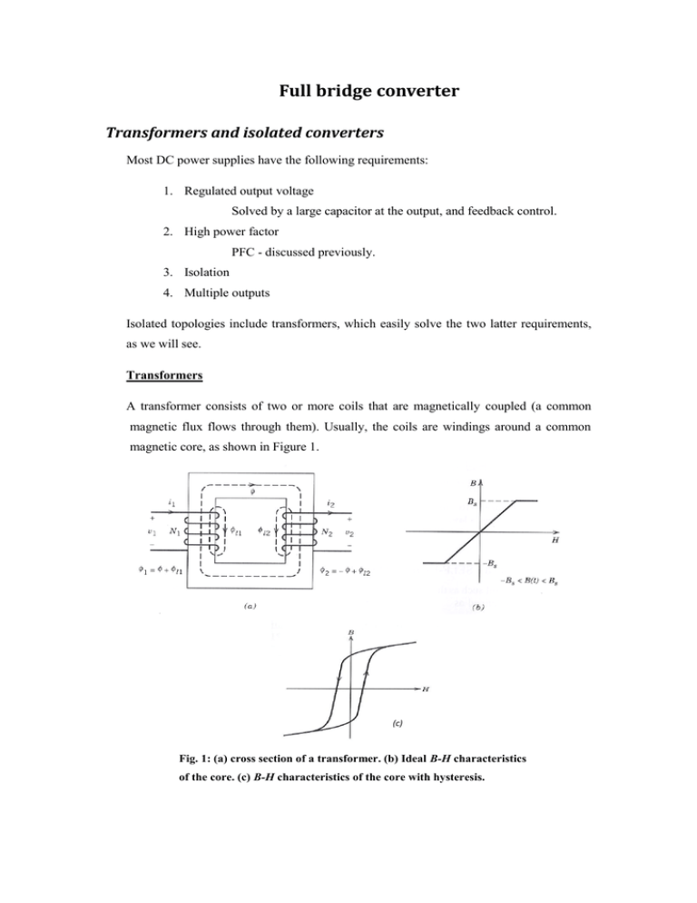
Full bridge converter Transformers and isolated converters Most DC power supplies have the following requirements: 1. Regulated output voltage Solved by a large capacitor at the output, and feedback control. 2. High power factor PFC - discussed previously. 3. Isolation 4. Multiple outputs Isolated topologies include transformers, which easily solve the two latter requirements, as we will see. Transformers A transformer consists of two or more coils that are magnetically coupled (a common magnetic flux flows through them). Usually, the coils are windings around a common magnetic core, as shown in Figure 1. (c) Fig. 1: (a) cross section of a transformer. (b) Ideal B-H characteristics of the core. (c) B-H characteristics of the core with hysteresis. Figure 2 shows the equivalent circuit of a transformer. Ideal transformers (Figure 2(b)) have the following properties: 1. No conduction losses in the windings ( 2. Infinite core permeability ( . . 3. No leakage fluxes ( Fig. 2: (a) Equivalent circuit for a non-ideal transformer with a lossless core and no hysteresis. (b) Equivalent circuit for an ideal transformer. In an ideal transformer, the current and voltage in both side are: Since there is no electrical connection between the two sides of the transformer (only magnetic one), it is isolated. Multiple outputs can be created by having multiple windings (in addition to the secondary winding), as shown in Figure 3. Fig. 3: Multiple outputs There are two kinds of isolated converter topologies: 1. Unidirectional core excitation – only the positive part of the B-H curve is used. Include: Flyback converter (shown in the lecture by Prof. Weiss), forward converter. 2. Bidirectional core excitation – both positive and negative parts of the B-H curve are used. Include: push-pull, half-bridge, full-bridge (explained below). An example - full-bridge converter Fig. 4: (a) Full-bridge converter. (b) voltage and current waveforms: the current of the inductor, is the voltage from the left side of the inductor to the middle tap of the secondary winding. and ( Figure 4 shows a full bridge converter where ( switched together alternatively for a time are pairs of switches, in a switching cycle (what is the switching frequency?). After each pair is turned off, there is a time interval switches are "off". When either pair is "on", ( ⁄ , and therefore when all Similarly, when all switches are "off", (assuming ideal diodes), and therefore In steady state, no energy is accumulated in the inductor, hence the time integral of the inductor voltage over one switching cycle is zero. Since where is the duty cycle (in this case, , we obtain: ). The figures are taken from: N. Mohan, T. M. Undeland and W. P. Robbins, Power electronics: converters, applications and design, 3rd ed., Hoboken, NY: John Wiley and Sons, Inc., 2003.

