www.ijraset.com
Volume 3 Issue I, January 2015
ISSN: 2321-9653
International Journal for Research in Applied Science & Engineering
Technology (IJRASET)
Wind Energy Power System Simulation for a
Remote Area Power Supply
K. Sathish Kumar#1, Prof. P. Pradeepa*2
#
PG Student, Power Electronics and Drives Department, CSI College of Engineering, Ketti
*
Professor, EEE Department, CSI College of Engineering, Ketti
Abstract— This work focuses on the designing and analysis of a wind energy power system for a Remote Area Power Supply
(RAPS). The system introduces a three phase ac-ac converter with an isolated high frequency-link for a wind energy
conversion system. The galvanic isolation is provided by the HF transformer. The transformer is having the magnetizing
inductance which improves power transfer capability. The capacitors are designed on both sides of the transformer to realize
ZVS for semiconductor devices and in addition to that it gives passive clamping. The design provides a reduced switch count
in order to reduce the losses. The power flow is bi-directional and thus power-flow can be reversed. The operation of the
three phase ac-ac converter is explained in eight modes of operation. The performance of the system is analysed using
MATLAB/ SIMULINK environment.
Keywords— Wind energy power system, ZVS, HF transformer, Remote Area Power System, RB-IGBT.
I. INTRODUCTION
With the developments in the power electronics, low-cost, high reliability and efficiency converters are available for wind
turbine (WT). This paper introduces an isolated zero voltage-switched three phase ac–ac converter with a high-frequency link
transformer for low and medium power applications. A small air-gapped high-frequency transformer acts as the key component
by providing galvanic isolation as well as transferring power using its magnetizing inductance. Two small capacitors are placed
on both sides of the transformer to realize zero-voltage switching for the semiconductor devices in addition to passive clamping
[1]. Therefore, the proposed topology is expected to be highly efficient and reliable due to soft switching operation and
exclusion of limited lifetime electrolytic capacitors. The basic operation of the converter includes eight modes and is described
in detail. Simulation results are provided to verify the performance of the proposed power converter.
II. ZVS ISOLATED HIGH FREQUENCY LINK AC-AC CONVERTER
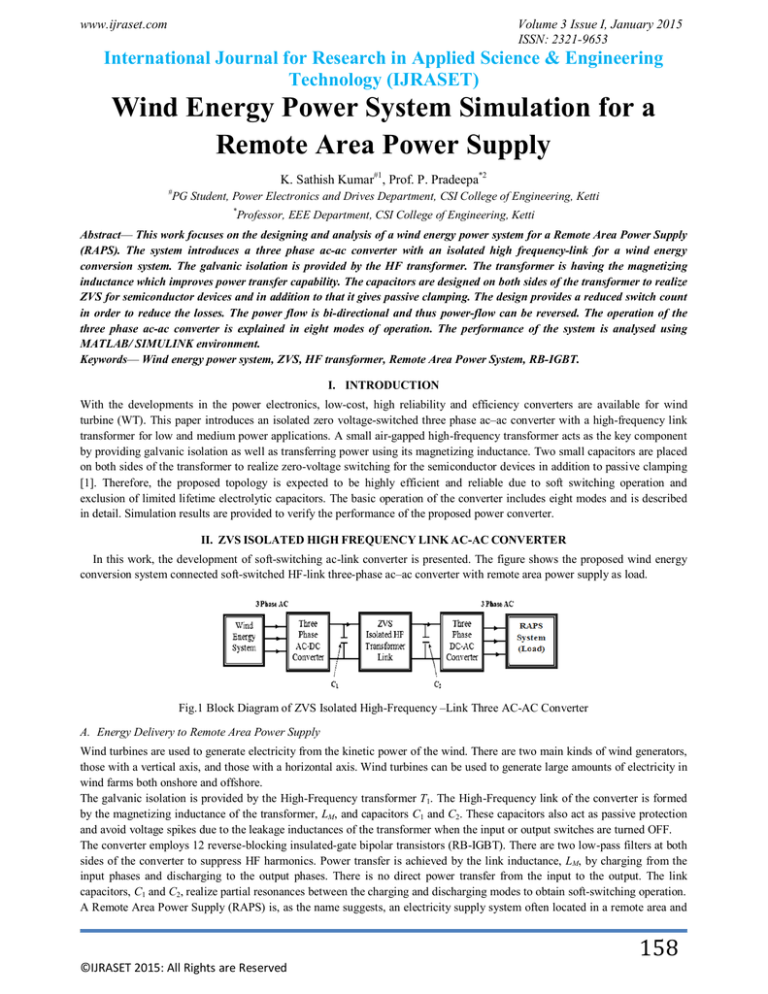
In this work, the development of soft-switching ac-link converter is presented. The figure shows the proposed wind energy
conversion system connected soft-switched HF-link three-phase ac–ac converter with remote area power supply as load.
Fig.1 Block Diagram of ZVS Isolated High-Frequency –Link Three AC-AC Converter
A. Energy Delivery to Remote Area Power Supply
Wind turbines are used to generate electricity from the kinetic power of the wind. There are two main kinds of wind generators,
those with a vertical axis, and those with a horizontal axis. Wind turbines can be used to generate large amounts of electricity in
wind farms both onshore and offshore.
The galvanic isolation is provided by the High-Frequency transformer T1. The High-Frequency link of the converter is formed
by the magnetizing inductance of the transformer, LM, and capacitors C1 and C2. These capacitors also act as passive protection
and avoid voltage spikes due to the leakage inductances of the transformer when the input or output switches are turned OFF.
The converter employs 12 reverse-blocking insulated-gate bipolar transistors (RB-IGBT). There are two low-pass filters at both
sides of the converter to suppress HF harmonics. Power transfer is achieved by the link inductance, LM, by charging from the
input phases and discharging to the output phases. There is no direct power transfer from the input to the output. The link
capacitors, C1 and C2, realize partial resonances between the charging and discharging modes to obtain soft-switching operation.
A Remote Area Power Supply (RAPS) is, as the name suggests, an electricity supply system often located in a remote area and
158
©IJRASET 2015: All Rights are Reserved
www.ijraset.com
Volume 3 Issue I, January 2015
ISSN: 2321-9653
International Journal for Research in Applied Science & Engineering
Technology (IJRASET)
unconnected to a major utility grid. These systems are also known as Stand-Alone Power Systems (SAPS).
III.CIRCUIT CONFIGURATION AND OPERATION PRINCIPLE
The soft-switched HF-link three-phase ac–ac converter is presented. Galvanic isolation is realized by the HF transformer T1 .
The HF link of the converter is formed by the magnetizing inductance of the transformer, LM , and capacitors C1 and C2 . These
capacitors also act as passive snubbers and avoid voltage spikes due to the leakage inductances of the transformer when the
input or output switches are turned OFF. An airgap may be used in the design of the transformer T1 to create a proper
magnetizing inductance [1].
Fig. 2 ZVS isolated HF-Link three-phase ac–ac converter
As the figure shows, the converter employs 12 reverse-blocking insulated-gate bipolar transistors (RB-IGBT). The RB-IGBT
has a symmetrical blocking voltage characteristic, which means that it can block both forward and reverse voltage in its off-state.
A series combination of a conventional IGBT and a diode can also make a reverse-blocking switch; nonetheless, individual RBIGBT has the advantage of lower total on-state voltage. Although the converter’s switches are unidirectional, the converter can
transfer power in both forward and reverse directions conveniently as will be shown later. There are two low-pass filters at both
sides of the converter to suppress HF harmonics. It should be noted that if the galvanic isolation is not required, the HF
transformer can be easily replaced by an inductor and capacitors, C1 and C2 can be merged [1].
Power transfer is achieved by the link inductance, LM , by charging from the input phases and discharging to the output
phases. There is no direct power transfer from the input to the output. The link capacitors, C1 and C2 , realize partial resonances
between the charging and discharging modes to obtain soft-switching operation [9].
A. RB-IGBT- Reverse Blocking- Insulated Gate Bipolar Junction Transistor
A series combination of a conventional IGBT and a diode can make a reverse-blocking switch. The main difference between the
reverse-blocking IGBT and the normal IGBT is that the RB-IGBT is capable of withstanding reverse voltage, i.e. negative
collector-emitter voltage. The figure shows the configuration of the RB-IGBT.
Fig.3 RB–IGBT- Reverse-Blocking Insulated Gate Bipolar Transistor
B. Principle of Operation
The proposed resonant HF-link converter is primarily a current-source converter and, as a result, the reference currents of the
output phases are necessary in the control scheme. The reference currents of the input phases are also required in this
converter’s control scheme. The input reference currents can be calculated using the output power and the estimated power loss
of the converter. For example, the input reference current of phase a can be given by:
ia−i,ref (t) = [√2 (Pout + Ploss) / √3VLi] sin (ωt)
(1)
where VLi is the input line rms voltage, Pout is the output active power, and Ploss is the estimated power loss of the converter. The
input reference currents of phases b and c can be calculated similarly. These reference currents should have the same frequency
and phase angle respective to their corresponding input phase voltages to achieve a unity input power factor. The operation of
the converter is not highly sensitive to the exact value of the power loss (Pout >> Ploss); however, to reach an accurate value of
the power loss, both the input and output active powers can be measured frequently.
The introduced converter has eight modes of operation in each link cycle. Basically, there are two modes for charging the link
inductance from the input phases and two modes for the link inductance to be discharged to the output phases. In addition, there
are four resonant modes between these active modes to create soft transition.
159
©IJRASET 2015: All Rights are Reserved
www.ijraset.com
Volume 3 Issue I, January 2015
ISSN: 2321-9653
International Journal for Research in Applied Science & Engineering
Technology (IJRASET)
C. Modes of Operation
Mode 1 (Charging)
The HF link is connected to an input phase pair with the highest instantaneous voltage by turning on two proper input-side
switches. Therefore, the link inductance, LM, charges in the positive direction. This mode is allowed to run until the average
current of one of the connected input phases meets its instantaneous reference value. The switches are turned OFF afterward.
Hence, the connected phase with the smaller instantaneous reference current magnitude meets its reference current in this mode.
Fig. 4 Mode 1
The other connected phase will be linked to the HF link in mode 3 again to meet its reference value accordingly. Owing to the
existence of the link capacitors, the link voltage, vL (t), drops slowly when the mode-1 switches are turned OFF. As a result, the
voltages of mode-1 switches increase slowly at their turn-off, which concludes that the switches are turned OFF at almost zero
voltage. This zero-voltage turnoff occurs similarly for all the converter’s other switches at all line and load conditions.
Mode 2 (Partial Resonance)
The link inductance starts to resonate with its parallel capacitors, and the link voltage starts to drop. This partial resonance
continues until the link voltage is equal to the second-highest instantaneous input line-to-line voltage.
Mode 3 (Charging)
Link is connected to an input phase pair with the second highest instantaneous voltage.
Fig. 5 Mode 3
Mode 4 (Partial Resonance)
All switches are turned off.
Fig. 6 Mode 2, 4 and 6
Mode 5 (Discharging)
Link is connected to an output phase pair with the lowest or 2nd-lowest instantaneous reference current difference.
Fig. 7 Mode 5
160
©IJRASET 2015: All Rights are Reserved
www.ijraset.com
Volume 3 Issue I, January 2015
ISSN: 2321-9653
International Journal for Research in Applied Science & Engineering
Technology (IJRASET)
Mode 6 (Partial Resonance)
The link components resonate together again until the link voltage equals the reflected voltage of the mode-7 phase pair.
Mode 7 (Discharging)
Link is connected to an output phase pair with the lowest or 2nd-lowest instantaneous reference current difference.
Fig. 8 Mode 7
Mode 8 (Considerable Resonance)
The HF-link components resonate together again. This partial resonance runs until the link voltage becomes equal to the highest
instantaneous input line-to-line voltage, and consequently, the converter goes to mode 1 with ZVS.
Fig. 9 Mode 8
Thus the design and operational modes of isolated ZVS High-Frequency-link AC-AC converter.
IV. SIMULATION MODELS AND SIMULATION RESULTS
A. Wind Power Generating System
Wind Energy is conversion of kinetic energy (i.e. energy of motion of the wind) into mechanical energy that can be utilized to
generate electricity.
Fig. 10 Wind Energy Power Generating System
B. Simulated Output Waveform from Wind Power System
Simulated Output Voltage Waveform from Asynchronous Generator (SCIG) for Wind Speed = 8m/s
Fig. 11 Waveform: Time(s) vs Three Phase Output Voltage from Asynchronous Generator(Vin)
161
©IJRASET 2015: All Rights are Reserved
www.ijraset.com
Volume 3 Issue I, January 2015
ISSN: 2321-9653
International Journal for Research in Applied Science & Engineering
Technology (IJRASET)
The output from generator is a three phase AC output. The magnitude of the output voltage is 208V AC.
Fig. 12 Waveform: Time(s) vs R Phase Output Voltage from Asynchronous Generator(Vin)
Fig. 13 Waveform: Time(s) vs R Phase Output Current from Asynchronous Generator (Iin)
The output current from generator is a three phase AC current. The above shown is the current waveform of R phase. The
magnitude of the output current is 150A AC.
Fig. 14 Waveform: Time(s) vs Power Output from Asynchronous Generator(Pin)
The magnitude of the output power from the wind power generating system is 18.5kW. Thus the above shown results of voltage,
current and power are the generated results from the wind power generating system. The asynchronous generator (Squirrel-Cage
Induction Generator) is used for conversion of mechanical to electrical energy.
C. Simulated Model of WECS connected ZVS Isolated HF-link Three-Phase AC-AC Converter
Fig. 15 Simulated Model of over-all system
D. Simulated Output from RB-IGBT Converter and HF-Link Transformer
162
©IJRASET 2015: All Rights are Reserved
www.ijraset.com
Volume 3 Issue I, January 2015
ISSN: 2321-9653
International Journal for Research in Applied Science & Engineering
Technology (IJRASET)
Fig. 16 Waveform: Time(s) vs Output Voltage from RB-IGBT Converter
The voltage output from the reverse blocking –IGBT converter is of magnitude 300V.
Fig. 17 Waveform: Time(s) vs Output Voltage from HF-link Transformer to RB-IGBT Inverter
The voltage output from the high frequency-link transformer to reverse blocking –IGBT converter is of magnitude 400V. The
transformer in the model is a single phase two winding transformer. By assuming the transformer to be ideal, the turns ratio is
taken as 1:1.
E. Simulated Output from RB-IGBT Converter and HF-Link Transformer
Fig. 18 Simulated Model of the Remote Area Power Supply (RAPS)
F. Simulated Output Waveform from Remote Area Power Supply
Fig. 19 Waveform: Time(s) vs Three Phase Output Voltage from Remote Area Power Supply acting as Load (Vout)
The output from Remote Area Power Supply which is acting as Load is a three phase AC output. The magnitude of the output
voltage is 380V AC.
163
©IJRASET 2015: All Rights are Reserved
www.ijraset.com
Volume 3 Issue I, January 2015
ISSN: 2321-9653
International Journal for Research in Applied Science & Engineering
Technology (IJRASET)
Fig. 20 Waveform: Time(s) vs R Phase Output Voltage from Remote Area Power Supply acting as Load (Vout)
This RAPS system is employed in areas where the long-term cost of connecting to a utility grid is more expensive than the lifecycle cost of RAPS.
Fig. 21 Waveform: Time(s) vs R Phase Output Current from Remote Area Power Supply (RAPS)
The output current from RAPS is a three phase AC current. The above shown is the current waveform of R phase. The
magnitude of the output current is 100A AC.
Fig. 22 Waveform: Time(s) vs Power Output from Remote Area Power Supply (RAPS)
The magnitude of the output power from Wind Power Generating System connected ZVS isolated HF-link three-phase ac–ac
converter is 19.2kW. Thus the above shown results of voltage, current and power are the generated results from the wind power
generating system connected ZVS isolated HF-link three-phase ac–ac converter.
V. CONCLUSION
An isolated HF-link three-phase ac–ac converter with soft-switching operation, a high input power factor, and bidirectional
power flow was introduced. Galvanic isolation is realized by a single-phase high frequency transformer, which is considerably
smaller than line-frequency isolation transformers. The magnetizing inductance of the air-gapped HF transformer and two small
capacitors on both sides of the transformer make the HF link of the converter. The transformer’s magnetizing inductance is
responsible for power transfer, and the link capacitors help to achieve ZVS as well as passive clamping. The detailed behaviour
of the converter was shown and the effectiveness of the proposed power topology was verified by means of the matlab
simulation.
REFERENCES
[1]
[2]
[3]
Hamidreza Keyhani and Hamid A. Toliyat, “Isolated ZVS High-Frequency-Link AC-AC Converter With a Reduced Switch Count,” IEEE Trans. Power
Electronics, vol. 29, no. 8, 1154-1161, August 2014.
R. Lai, F. Wang, R. Burgos, Y. Pei, D. Boroyevich, B. Wang et al., “A systematic topology evaluation methodology for high-density three-phase PWM
AC–AC converters,” IEEE Trans. Power Electron., vol. 23, no. 6, pp. 2665–2680, Nov. 2008.
G. Gong, M. L. Heldwein, U. Drofenik, J. Minibock, K. Mino et al., “Comparative evaluation of three-phase high-power-factor AC–DC converter
164
©IJRASET 2015: All Rights are Reserved
www.ijraset.com
Volume 3 Issue I, January 2015
ISSN: 2321-9653
International Journal for Research in Applied Science & Engineering
Technology (IJRASET)
[4]
[5]
[6]
[7]
[8]
[9]
concepts for application in future more electric aircraft,” IEEE Trans. Ind. Electron., vol. 52, no. 3, pp. 727–737, Jun. 2005.
J. W. Kolar, T. Friedli, J. Rodriguez, and P. W.Wheeler, “Review of threephase PWM AC–AC converter topologies,” IEEE Trans. Ind. Electron., vol. 58,
no. 11, pp. 4988–5006, Nov. 2011.
P. W. Wheeler, J. Rodriguez, J. C. Clare, L. Empringham, and A. Weinstein, “Matrix converters: A technology review,” IEEE Trans. Ind. Electron., vol.
49, no. 2, pp. 276–288, Apr. 2002.
Alan and T. A. Lipo, “Starter/generator employing resonant-converterfed induction machine. I. Analysis,” IEEE Trans. Aerosp. Electron. Syst., vol. 36,
no. 4, pp. 1309–1328, Oct. 2000.
D. Kim and G. H. Cho, “New bilateral zero voltage switching AC–AC converter using high frequency partial-resonant link,” in Proc. 16th Ind. Electron.
Soc., 1990, pp. 857–862.
Y. Otani, T. Isobe, and R. Shimada, “A new topology of direct AC–AC converter with soft-switching based on a MERS pulse link concept,” in Proc.
Power Electron. Appl., 2011, pp. 1–10.
H. Keyhani, H. A. Toliyat, M. Todorovic, R. Lai, and R. Datta, “Isolated soft switching HFAC-link 3-phase AC–AC converter using a single-phase HF
transformer,” in Proc. 38th Annu. Conf. IEEE Ind. Electron. Soc., Oct. 2012, pp. 25–28.
©IJRASET 2015: All Rights are Reserved
165


