IB 1152 Troubleshooting Silicon Controlled Rectifiers
advertisement

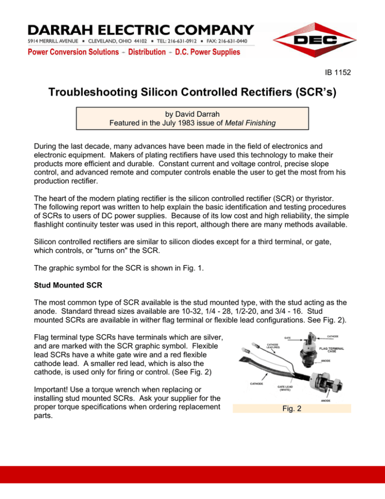
IB 1152 Troubleshooting Silicon Controlled Rectifiers (SCR’s) by David Darrah Featured in the July 1983 issue of Metal Finishing During the last decade, many advances have been made in the field of electronics and electronic equipment. Makers of plating rectifiers have used this technology to make their products more efficient and durable. Constant current and voltage control, precise slope control, and advanced remote and computer controls enable the user to get the most from his production rectifier. The heart of the modern plating rectifier is the silicon controlled rectifier (SCR) or thyristor. The following report was written to help explain the basic identification and testing procedures of SCRs to users of DC power supplies. Because of its low cost and high reliability, the simple flashlight continuity tester was used in this report, although there are many methods available. Silicon controlled rectifiers are similar to silicon diodes except for a third terminal, or gate, which controls, or "turns on" the SCR. The graphic symbol for the SCR is shown in Fig. 1. Stud Mounted SCR The most common type of SCR available is the stud mounted type, with the stud acting as the anode. Standard thread sizes available are 10-32, 1/4 - 28, 1/2-20, and 3/4 - 16. Stud mounted SCRs are available in wither flag terminal or flexible lead configurations. See Fig. 2). Flag terminal type SCRs have terminals which are silver, and are marked with the SCR graphic symbol. Flexible lead SCRs have a white gate wire and a red flexible cathode lead. A smaller red lead, which is also the cathode, is used only for firing or control. (See Fig. 2) Important! Use a torque wrench when replacing or installing stud mounted SCRs. Ask your supplier for the proper torque specifications when ordering replacement parts. ISO 9001:2000 Certified Fig. 2 www.darrahelectric.com Darrah Electric Company Page 2 of 4 Disk or Hockey Puck SCR Another type of SCR available is the disk or hockey puck. These are identified on terms of their approximate height and width, i.e., 1 x 2 hockey puck SCR (See Fig. 3) The small red lead (cathode), common with the metal flange, identifies which side is the cathode. The white lead (gate) will usually extend from the glass ceramic. Fig. 3 Important! The mounting and tightening of hockey puck SCRs are extremely critical. Alternate back and forth between the clamp mounting bolts, and tighten slowly. Make sure that the mounting surfaces are clean and smooth. Be sure to use the correct heat sink compound. For best results, ask your supplier for specific instructions when ordering replacement parts. Testing SCRs For best results, the stud mounted SCR should be removed from the unit and bench tested; however, it can be tested while still in the rectifier by disconnecting the cathodes and gate terminals. Hockey puck SCRs should be removed for testing. The SCR's are most easily and accurately tested with a flashlight continuity tester. Test Equipment: A simple continuity tester. A modified flashlight, as shown in Fig. 4, is best because it can turn on, or fire most SCRs. Make sure that the red lead of the tester is positive, and the black lead is negative. Reversing the batteries will change the polarity of the leads. (See Fig. 4) Fig. 4 Stud Mounted – Flag Terminal and Flexible Lead: 1. Attach the negative (black) lead of the tester to the cathode lead of the SCR. 2. Attach the positive (red) lead of the tester to the anode (stud) of the SCR. 3. Turn the flashlight on. The bulb should not light. If the bulb lights, you have a shorted SCR, and it should be replaced. ISO 9001:2000 Certified www.darrahelectric.com Darrah Electric Company Page 3 of 4 4. Next, touch the gate (white) lead to the SCR anode (stud). The bulb should light and stay lit, even when the gate lead is disconnected from the anode. (See Fig. 5) An Open SCR will not light the flashlight A good SCR should light the tester until the cathode (red) lead is jumped to the anode, which will turn the SCR off. Fig. 5 Disk or Hockey Puck SCR Disk type SCRs should be tested with pressure applied to both the anode and cathode. Mount a standard "C" clamp in a vise for best results. 1. Mount the SCR in the clamp. Be sure to use plat material between the clamp and the anode and cathode. 2. Attach the negative (black) lead of the tester of the cathode (red) lead of the SCR. 3. Attach the positive (red) lead of the tester to the anode of the SCR. Fig 6 4. Turn the flashlight on. Tighten the "C" clamp to the recommended pressure. If the bulb lights, you have a shorted SCR. 5. Next, touch the gate (white) lead to the SCR anode, or the positive (red) lead of the tester. The bulb should light. An open SCR will not light the bulb of the tester. A good SCR should light the tester until the cathode is jumped to the anode, turning the SCR off. Thermo-Compound Because thermo-compounds vary with respect to their base metal junctions and uses, care should be taken to select the proper compound when mounting SCRs to their heat sinks. Ask your supplier for information concerning thermo-compounds when ordering replacement parts. Replacements When purchasing replacement SCRs, keep these points in mind: the size of the device can generally be used to judge its current rating. With stud mounted SCRs, the head of the device, as well as the stud, should be of the same size. In hockey puck SCRs, the anode-cathode ISO 9001:2000 Certified www.darrahelectric.com Darrah Electric Company Page 4 of 4 conduction surface diameter of the replacement should match the diameter of the original. The amperage rating of the replacement part must at least meet the amperage rating of the original. Voltage, or peak reverse voltage (PRV), is the amount of reverse voltage the SCR can handle without damage to itself in the blocking direction. Make sure that the voltage rating of the replacement SCR is at least 3.5 times the applied voltage to the SCR. Buying an SCR with a higher PRV will give you added protection against voltage spikes. ISO 9001:2000 Certified www.darrahelectric.com


