Single Phase - 5 to 25kVA
advertisement
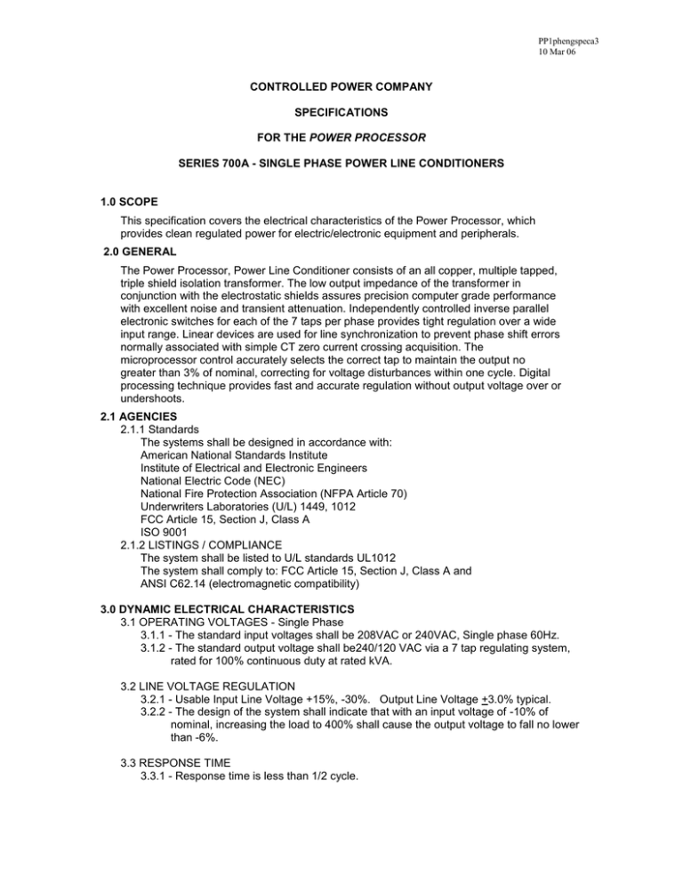
PP1phengspeca3 10 Mar 06 CONTROLLED POWER COMPANY SPECIFICATIONS FOR THE POWER PROCESSOR SERIES 700A - SINGLE PHASE POWER LINE CONDITIONERS 1.0 SCOPE This specification covers the electrical characteristics of the Power Processor, which provides clean regulated power for electric/electronic equipment and peripherals. 2.0 GENERAL The Power Processor, Power Line Conditioner consists of an all copper, multiple tapped, triple shield isolation transformer. The low output impedance of the transformer in conjunction with the electrostatic shields assures precision computer grade performance with excellent noise and transient attenuation. Independently controlled inverse parallel electronic switches for each of the 7 taps per phase provides tight regulation over a wide input range. Linear devices are used for line synchronization to prevent phase shift errors normally associated with simple CT zero current crossing acquisition. The microprocessor control accurately selects the correct tap to maintain the output no greater than 3% of nominal, correcting for voltage disturbances within one cycle. Digital processing technique provides fast and accurate regulation without output voltage over or undershoots. 2.1 AGENCIES 2.1.1 Standards The systems shall be designed in accordance with: American National Standards Institute Institute of Electrical and Electronic Engineers National Electric Code (NEC) National Fire Protection Association (NFPA Article 70) Underwriters Laboratories (U/L) 1449, 1012 FCC Article 15, Section J, Class A ISO 9001 2.1.2 LISTINGS / COMPLIANCE The system shall be listed to U/L standards UL1012 The system shall comply to: FCC Article 15, Section J, Class A and ANSI C62.14 (electromagnetic compatibility) 3.0 DYNAMIC ELECTRICAL CHARACTERISTICS 3.1 OPERATING VOLTAGES - Single Phase 3.1.1 - The standard input voltages shall be 208VAC or 240VAC, Single phase 60Hz. 3.1.2 - The standard output voltage shall be240/120 VAC via a 7 tap regulating system, rated for 100% continuous duty at rated kVA. 3.2 LINE VOLTAGE REGULATION 3.2.1 - Usable Input Line Voltage +15%, -30%. Output Line Voltage +3.0% typical. 3.2.2 - The design of the system shall indicate that with an input voltage of -10% of nominal, increasing the load to 400% shall cause the output voltage to fall no lower than -6%. 3.3 RESPONSE TIME 3.3.1 - Response time is less than 1/2 cycle. 3.4 CORRECTION TIME 3.4.1 - The output voltage is corrected within 1 cycle. 3.5 LOAD REGULATION 3.5.1 - The output is maintained to within 2.5% of nominal or less, from no load to full load. 3.5.2 - Output impedance shall be less than 3% 3.6 OPERATING FREQUENCY 3.6.1 - 60 Hertz + 3 Hertz 3.7 HARMONIC DISTORTION 3.7.1 - Less than 1% THD added to the output waveform under any dynamic linear loading conditions presented to the line regulator. 3.8 OVERLOAD RATING 3.8.1 - 200% for ten seconds. 3.8.2 - 1000% for one cycle. 3.9 NOISE ATTENUATION 3.9.1 - Common mode noise attenuation is typically 140 dB or greater. 3.9.2 - Transverse mode noise attenuation is 3 dB down at 300 Hertz, 40 dB down per decade to below 50 dB with a resistive load. 3.10 AUDIBLE NOISE 3.10.1 - Not to exceed 55dB measured @1 meter 3.11 EFFICIENCY 3.11.1 - 98% Typical at full load. 3.12 POWER FACTOR - Three Phase 3.12.1 - Input power factor shall be greater than .95 with a resistive load. 4.0 MAIN TRANSFORMER 4.1 BASIC CONSTRUCTION 4.1.1 - The transformer windings are of all copper conductor construction with separate primary and secondary isolated windings. 4.2 MAGNETIC 4.2.1 - Grain oriented, M6 grade, stress relieved silicon transformer steel is utilized to minimize losses and provide maximum efficiency. Flux density will not exceed 15k gauss. 4.3 INSULATION 4.3.1 - Class N (200° C) insulation is utilized throughout. 4.4 SHIELDING 4.4.1 - The transformer has multiple (three) copper shields to minimize inner winding capacitance, transient and noise coupling between primary and secondary windings. 4.5 COOLING 4.5.1 - The transformer is designed for natural convection cooling. 4.6 OPERATING TEMPERATURE 4.6.1 - The system operating range: 0 to 40 degrees C, no de-rating required at 095% relative humidity non-condensing. 5.0 MAIN INPUT BREAKER A main input molded case, thermal magnetic circuit breaker, rated at 125 % of the full load input current, is furnished as an integral part of the unit. 6.0 BY-PASS SWITCH (Optional) A manually operated rotary bypass switch provides bypassing of the regulator portion of the Power Line Conditioner. The regulator can be either on-line or bypassed with one turn of the switch. The transformer and suppression circuitry remains in the circuit when in the bypass mode. 7.0 MONITORING 7.1 ALERT LIGHT 7.1.1 - An indicator light shall annunciate that the output has been disabled by one of the following conditions: (1) Transformer over-temperature (2) SCR thermal over-temperature 8.0 CABINET 8.1 TERMINATION 8.1.1 - Termination is rear access with input and output connections via a terminal strip. (Maximum current dependent) 8.2 VENTILIATION 8.2.1 - Ventilation originates from the bottom of the cabinet and exhausts at the rear of the cabinet. 8.3 MOBILITY 8.3.1 - The Power Line Conditioner cabinets are equipped with fixed casters. Each caster is located so as not to exceed 600 lbs/sq inch on any one caster. 8.4 ACCESSABILITY 8.4.1 - The cabinet is constructed with lift off panels for ease of access. 9.0 CONTROLS The control portion of the cabinet containing the circuit boards and connection to the semi- conductor devices is separate from the transformer and input / output termination. 10.0 WARRANTY Standard commercial one year warranty.


