Randomly Polarized Light Effects: HeNe Laser Research
advertisement

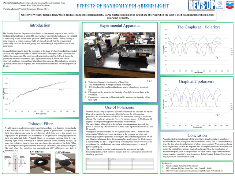
Physics Group: Kathryn Morales, Leslie Soledad, Michael Medrano, Jerod Moore, Kian Talaei, Geoffrey Bartz Faculty Advisors: Vladimir Gasparyan, Thomas Meyer Objective: We have tested a laser, which produces randomly polarized light. Large fluctuations in power output are observed when the laser is used in applications which include polarizing elements. Introduction Experimental Apparatus The Graphs at 1 Polarizer The Faraday Rotation Experiment (see Poster in this session) requires a laser, which produces polarized light at about 650 nm. The laser was initially broken, so we replaced it temporarily with a helium-neon gas laser (JDS Uniphase model 1508-0), adding an extra polarizer to obtain polarized light. We then observed that the power output produced by the laser fluctuated greatly over time making it impossible to use in this experiment. . Because the laser is randomly polarized, without a polarizer, we observed slow changes in intensity of the light emitted from it. We decided therefore to study the properties of the laser. We first looked at the output of the laser with a photometer (PASCO OS-8020) and a fibre optics cable to transfer the light to the photometer. The experimental setup is shown in Fig. 1. Fig. 2 shows the photometer response to the laser light. A gradual increase in power with time is observed, reaching a constant level after about three minutes. This indicates a warming up period for the laser is required. The manufacturer recommends a warm up period of 10 min. Fig. 3 Fig. 1 1. Volt meter- Measures the intensity of laser light. 2. Two polaroid filters- Changes intensity of the light. 3. JDS Uniphase Helium Neon Gas Laser- source of randomly polarized light 4. Fibre optic cable- transmits the intensity of the light from the laser to the volt meter 5. Photometer- connected to fiber optic cable measures the intensity of the laser light. Graph at 2 polarizers Use of Polarizers Polaroid Filter A light wave is an electromagnetic wave that oscillates in a direction perpendicular to the direction of the wave. This defines a plane of polarization. In unpolarized light, those planes may point in any direction while light waves that remain in a single plane are polarized (A). Polarization is the practice of changing unpolarized light into polarized light. Polaroid filters, or polarizers, polarize light by only allowing light waves vibrating in a certain direction while blocking the rest. By using two polarizers back to back, you can change the intensity of the light. When the second polarizer is parallel to the first one (0˚ difference), the intensity is highest (B), and when the polarizers are perpendicular (90˚ difference), no light is transmitted (C). B. 0˚ difference A. C. 90˚ difference We then placed a single layer of a polarizer in between the laser and the optical fibre cable input to the photometer. (See the box on the left regarding polarizers) We measured the variation in the photometer reading as a function of time. The results are shown in Fig. 3. For various angles ( 0, 30, 60, and 90 degrees) of the polarizing plane with respect to the vertical. The main feature of the plots is the definite time dependence, in which the power is reduced by a factor between 0.9 and 2 and a period of between 20 and 80 seconds. We repeated the measurement for 30 degrees several times. The results are shown in the Table below. Large variations in the response are observed. We finally placed two polarizers in the light’s path with the angles of 0, 30, 60, and 90 degrees between them. We expect only a small output for 90 degrees as is confirmed by the data. The periodicity of the response varies between 20-30 seconds and the ratio between maximum and minimum power is about 2 period (See Fig. 4). The results indicate a certain randomness in the response of our light measuring system, which seems to indicate that our laser is either randomly or circularly polarized. Trial Period (sec) Ratio 1 28.2 3.3 2 30.5 3.2 3 47.7 3.0 4 56.9 2.9 5 70.4 2.9 Conclusion According to the manufacturer of the laser, the polarization state of a randomly polarized HeNe laser changes on nanosecond time scales. This is called coherence time, the time when the polarization of a laser stays constant. When averaged over much larger times, such as the response time of the photometer and associated volt meter, the emitted light appears randomly polarized. Thus the introduction of polarization optics, such as the polarizers we used, causes large variations in the power output as recorded by our photometer. In the Faraday Rotation Experiment only a polarized laser should be used. References 1. Poster Faraday Rotation at this session 2. JDS Uniphase Helium Neon Gas Laser, Model 1508-0 3. http://www.physicsclassroom.com/class/light/Lesson-1/Polarization


