Episode 311-3: Exploring waveforms with an oscilloscope (Word, 49 KB)
advertisement
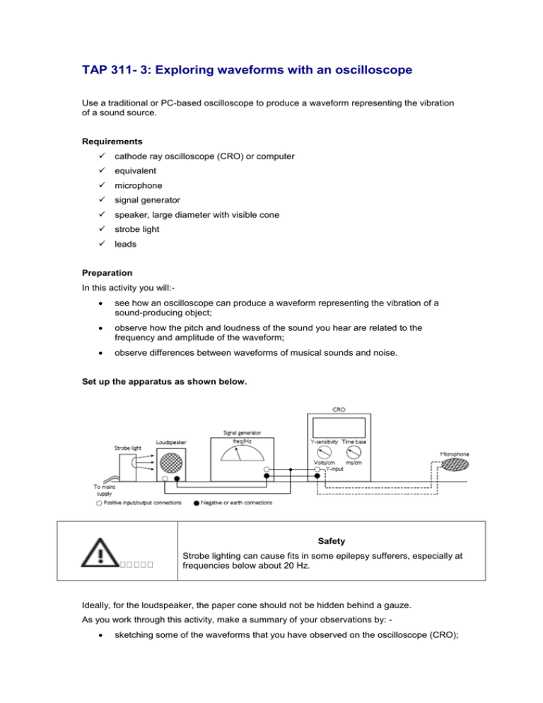
TAP 311- 3: Exploring waveforms with an oscilloscope Use a traditional or PC-based oscilloscope to produce a waveform representing the vibration of a sound source. Requirements cathode ray oscilloscope (CRO) or computer equivalent microphone signal generator speaker, large diameter with visible cone strobe light leads Preparation In this activity you will: see how an oscilloscope can produce a waveform representing the vibration of a sound-producing object; observe how the pitch and loudness of the sound you hear are related to the frequency and amplitude of the waveform; observe differences between waveforms of musical sounds and noise. Set up the apparatus as shown below. Safety Strobe lighting can cause fits in some epilepsy sufferers, especially at frequencies below about 20 Hz. Ideally, for the loudspeaker, the paper cone should not be hidden behind a gauze. As you work through this activity, make a summary of your observations by: sketching some of the waveforms that you have observed on the oscilloscope (CRO); describing how changing the frequency and loudness affects the signal waveform; describing the main differences between waveforms of musical sounds and noises; answering the questions in each section as you go along. Your summary should be as concise and accurate as possible, using correct scientific terms where appropriate. Oscillations Switch off the time base of the oscilloscope. Adjust the brilliance and focus buttons on the oscilloscope until you produce a sharp, bright spot in the centre of the screen. Start with the signal generator at a very low frequency around 1–2 Hz. Set the amplitude of the signal large enough to enable you to see the speaker cone moving (if only slightly) and adjust the Y-input sensitivity of the oscilloscope until you can see that the visible signal covers around half the screen or more. What do you observe the spot of the oscilloscope to be doing? How is its movement related to the movement of the speaker cone? Change the signal to around 40 Hz and use the strobe light facing the speaker cone, adjusting its flash rate until you see the cone appear to slow down. This illustrates that the speaker cone still moves in a similar way to the way it moved at 1–2 Hz at much higher frequencies. You should be able to get it to appear almost to stop, if not completely. What is now the link between the flash rate of the strobe and the frequency of the speaker? Increase the frequency of the signal generator to give a pleasant output sound from the speaker at around 200 Hz. Explain what you observe now on the oscilloscope screen. Waveforms Switch on the time base and gradually adjust it until you see a recognisable wave pattern on the screen with several cycles. (You will need to adjust the X-shift so that the pattern is covering most of the screen.) The wave pattern can be thought of as a graph. What do the vertical and horizontal axes of this graph represent in terms of the oscillation producing the sound? Using the signal generator controls, try altering the frequency and loudness (not too loud!) of the sound and observe the effect it has on the CRO trace. Switch off the signal generator and disconnect it and the loudspeaker from the CRO. Replace it with a microphone connected to the CRO Y-input. Try whistling, singing and speaking into the microphone – you might have to make adjustments to the Y-sensitivity to see a clear effect on the screen. What similarities and differences exist between the waveforms that you have produced? Which sorts of sounds give regular-shaped traces? Can you suggest why this is the case? Observe traces from other sounds on the CRO and consider their patterns. Practical advice If, as is hoped, students can perform this exploration themselves, they may need some guidance in using an oscilloscope first – they need to be familiar with relevant terms such as time base, brilliance, focus, Y-gain and X-shift. They may also need guidance in using a signal generator. It is nice, but not essential, to see the speaker cone vibrating under a strobe light. If large amplitude vibrations are planned, use an old speaker in case of damage. An extra demonstration which generates a displacement–time graph for an oscillation uses a rotary potentiometer connected to a stiff pendulum such as a weighted metre rule. The varying voltage obtained can be displayed on an oscilloscope or, with suitable software, on a computer screen. Point out that the graph shows angular displacement. Safety Strobe lighting can cause fits in epilepsy sufferers, especially at frequencies below about 20 Hz. Do not use the strobe light if you suffer from photo-induced epilepsy. External reference This activity is taken from Salters Horners Advanced Physics, section TSOM, activity 2

