________________________Solution________________________
advertisement
UC Berkeley
College of Engineering
EECS Department
EECS150
Spring 2002
J. Wawrzynek
Prepared by Wen Hui Guan
Quiz #6
Name: ________________________Solution________________________
SID: ____________________________________Lab section number: _____________
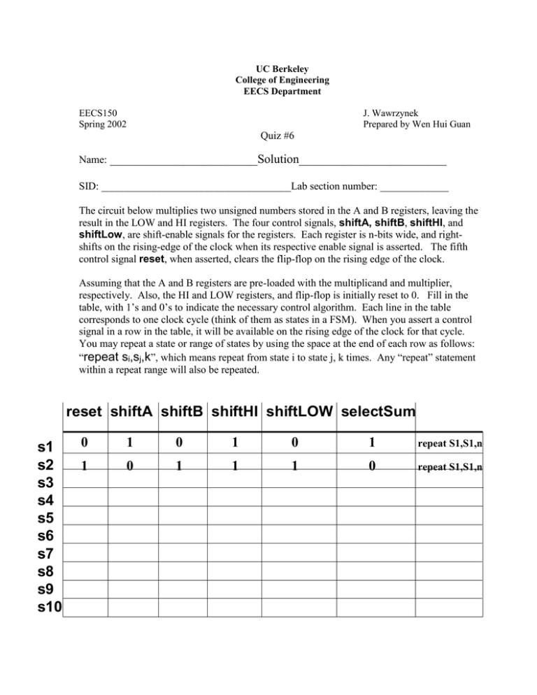
The circuit below multiplies two unsigned numbers stored in the A and B registers, leaving the
result in the LOW and HI registers. The four control signals, shiftA, shiftB, shiftHI, and
shiftLow, are shift-enable signals for the registers. Each register is n-bits wide, and rightshifts on the rising-edge of the clock when its respective enable signal is asserted. The fifth
control signal reset, when asserted, clears the flip-flop on the rising edge of the clock.
Assuming that the A and B registers are pre-loaded with the multiplicand and multiplier,
respectively. Also, the HI and LOW registers, and flip-flop is initially reset to 0. Fill in the
table, with 1’s and 0’s to indicate the necessary control algorithm. Each line in the table
corresponds to one clock cycle (think of them as states in a FSM). When you assert a control
signal in a row in the table, it will be available on the rising edge of the clock for that cycle.
You may repeat a state or range of states by using the space at the end of each row as follows:
“repeat si,sj,k”, which means repeat from state i to state j, k times. Any “repeat” statement
within a repeat range will also be repeated.
reset shiftA shiftB shiftHI shiftLOW selectSum
s1
s2
s3
s4
s5
s6
s7
s8
s9
s10
0
1
0
1
0
1
repeat S1,S1,n
1
0
1
1
1
0
repeat S1,S1,n
Bit-serial Multiplier
shiftA
A register
carry
shiftB
FA
D-FF
B register
reset
sum
shiftHI
0
1
HI register
shiftLOW
LOW register
selectSum
The easy way to look it is as follows (let n = 4):
1011
x 0101
--------------1011
0000
1011
0000
---------------0110111
// registerA
// registerB
// We know that for each bit in B register, we need to shift A register n times, and choose carry at the end of each n
// iterations. But each bit for the LOW register only available after each n-shift of HI register; otherwise, the bits
// for the LOW register would be off. So we have:
for (i = 0; i < n, i++) {
For (j = 0; j < n; j++) {
reset
shiftA
shiftB
shiftHI
shiftLOW
selectSUM
}
reset
= 1,
shiftA
= 0,
shiftB
= 1,
shiftHI
= 1,
shiftLOW
= 1,
selectSUM
= 0;
}
= 0,
= 1,
= 0,
= 1,
= 0,
= 1;
// The main part is to correctly setup the inner and outer loops. Note that either register A or
// register B can be the multiplier. So this designation has to be consistent for both inner and
// outer loops.

