Non-linear Seismic Dynamic Response of Isolated Highway Viaducts under
advertisement

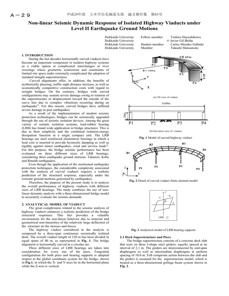
A-29 平成20年度 土木学会北海道支部 論文報告集 第65号 Non-linear Seismic Dynamic Response of Isolated Highway Viaducts under Level II Earthquake Ground Motions Hokkaido University Hokkaido University Hokkaido University Hokkaido University Toshiro Hayashikawa Javier Gil Belda Carlos Mendez Galindo Takashi Matsumoto Student member Member 3@ 40m P1 P2 R = 100m Z P3 Y P4 X (a) 3D view of viaduct 20m 3x40m P1 P3 P2 P4 (b) Elevation view of viaduct Fig. 1 Model of curved highway viaduct B3 B2 B4 B1 Z Y P1 P3 P2 P4 X Fig. 2 Detail of curved viaduct finite element model F K2 F1 K1 2. ANALYTICAL MODEL OF VIADUCT The great complexness related to the seismic analysis of highway viaducts enhances a realistic prediction of the bridge structural responses. This fact provides a valuable environment for the non-linear behavior due to material and geometrical non-linearities of the relatively large deflection of the structure on the stresses and forces. The highway viaduct considered in the analysis is composed by a three-span continuous seismically isolated deck. The overall viaduct length of 120 m has been divided in equal spans of 40 m, as represented in Fig. 1. The bridge alignment is horizontally curved in a circular arc. Three different sizes of LRB bearings are taken into consideration for every one of the piers. Tangential configuration for both piers and bearing supports is adopted respect to the global coordinate system for the bridge, shown in Fig.1, in which the X- and Y-axes lie in the horizontal plane while the Z-axis is vertical. m 20 1. INTRODUCTION During the last decades horizontally curved viaducts have become an important component in modern highway systems as a viable option at complicated interchanges or river crossings where geometric restrictions and constraints of limited site space make extremely complicated the adoption of standard straight superstructures. Curved alignments offer, in addition, the benefits of aesthetically pleasing, traffic sight distance increase, as well as economically competitive construction costs with regard to straight bridges. On the contrary, bridges with curved configurations may sustain severe damage owing to rotation of the superstructure or displacement toward the outside of the curve line due to complex vibrations occurring during an earthquake1). For this reason, curved bridges have suffered severe damage in past earthquakes. As a result of the implementation of modern seismic protection technologies, bridges can be seismically upgraded through the use of seismic isolation devices. Among the great variety of seismic isolation systems, lead-rubber bearing (LRB) has found wide application in bridge structures. This is due to their simplicity and the combined isolation-energy dissipation function in a single compact unit. The LRB bearings are steel reinforced elastomeric bearings in which a lead core is inserted to provide hysteretic damping as well as rigidity against minor earthquakes, wind and service loads2). For this purpose, the bridge seismic performance has been evaluated on three different sizes of LRB bearings, considering three earthquake ground motions: Takatori, Kobe and Rinaldi earthquakes. Even though the application of the mentioned earthquake protection techniques, the considerable complexity associated with the analysis of curved viaducts requires a realistic prediction of the structural response, especially under the extreme ground motions generated by earthquakes. Therefore, the purpose of the present study is to analyze the overall performance of highway viaducts with different sizes of LRB bearings. The study combines the use of nonlinear dynamic analysis with a three-dimensional bridge model to accurately evaluate the seismic demands. Fellow member (c) LRB d L Fig. 3 Analytical model of LRB bearing supports 2.1 Deck Superstructure and Piers The bridge superstructure consists of a concrete deck slab that rests on three I-shape steel girders, equally spaced at an interval of 2.1 m. The girders are interconnected by end-span diaphragms as well as intermediate diaphragms at uniform spacing of 10.0 m. Full composite action between the slab and the girders is assumed for the superstructure model, which is treated as a three-dimensional grillage beam system shown in Fig. 2. 平成20年度 土木学会北海道支部 論文報告集 第65号 G1 G2 G3 maximum displacements (m) 0.5 0.4 0.3 0.2 0.1 L1 L2 TAK L3 L1 L2 KOB L3 L1 L2 RIN B4 B3 B2 B1 B4 B3 B2 B1 B4 B3 B2 B1 B4 B3 B2 B1 B4 B3 B2 B1 B4 B3 B2 B1 B4 B3 B2 B1 B4 B3 B2 B1 B4 B3 B2 B1 0.0 L3 Fig. 4. Deck displacements for Takatori, Kobe and Rinaldi earthquakes in every girder The deck weight is supported on four hollow box section steel piers of 20m height, designed according to the seismic code in Japan1). Characterization of structural pier elements is based on the fiber element modelization where the inelasticity of the flexure element is accounted by the division of the cross-section into a discrete number of longitudinal and transversal fiber regions with constitutive model based on uniaxial stress-strain relationship for each zone. The element stress resultants are determined by integration of the fiber zone stresses over the cross section of the element. At the pier locations the bridge deck is modeled in the transverse direction as a rigid bar of length equal to the deck width. This transverse rigid bar is used to model the interactions between deck and pier motions3). 2.2 Bearing Supports The section is supported on four pier units (P1, P2, P3 and P4) by LRB bearings. The three different types of properties will be hereby called L1, L2 and L3. In the top of every pier a set of three bearings is installed, these bearings will be called B1, B2, B3 and B4 in according to the pier numeration. The viaduct consists of three girders, that have been called G1, G2 and G3, being G1 the one that is inside the curvature and G3 the one that is outside the curvature as its showed in Fig.2. Orientation of LRB bearings is such as to allow for longitudinal movements. LRB bearing supports are represented by the bilinear force-displacement hysteresis loop presented in Fig. 3. The principal parameters that characterize the analytical model are the pre-yield stiffness K1, corresponding to combined stiffness of the rubber bearing and the lead core, the stiffness of the rubber K2 and the yield force of the lead core F1. The devices are designed for optimum yield force level to superstructure weight ratio (F1/W = 0.1) and pre-yield to post-yield stiffness ratio (K1/ K2 = 10.0), which provide maximum seismic energy dissipation capacity as well as limited maximum deck displacements4). It is also noted that properties of LRB bearings have been selected depending on the differences in dead load supported from the superstructure. The objective is to attract the appropriate proportion of non-seismic and seismic loads according to the resistance capacity of each substructure ensuring a near equal distribution of ductility demands over all piers. Furthermore, displacements of LRB bearings have been partially limited for all the viaducts, through the installation of lateral side stoppers. 3. METHOD OF ANALYSIS The analysis on the highway viaduct model is conducted using an analytical method based on the elasto-plastic finite displacement dynamic response analysis. The tangent stiffness matrix, considering both geometric and material nonlinearities, is adopted in this study, being the cross sectional properties of the nonlinear elements prescribed by using fiber elements. The stress-strain relationship of the beam-column element is modeled as a bilinear type. The yield stress is 235.4 MPa, the elastic modulus is 200 GPa and the strain hardening in plastic area is 0.01. The implicit time integration Newmark scheme is formulated and used to directly calculate the responses, while the NewtonRaphson iteration method is used to achieve the acceptable accuracy in the response calculations. The damping of the structure is supposed a Rayleigh’s type, assuming a damping coefficient of the first two natural modes of 2%. To assess the seismic performance of the viaduct, the nonlinear bridge model is subjected to the longitudinal (L), transverse (T), and vertical (V) components of a strong ground motion records from the Takatori (TAK) and Kobe (KOB) Stations during the 1995 Kobe Earthquake, as well as Rinaldi (RIN) Station, from the Northridge Earthquake. The longitudinal earthquake component shakes the highway viaduct parallel to the X-axis of the global coordinate system, while the transverse and vertical components are acting in the Y- and Z-axes, respectively. The large magnitude records from the 1995 Kobe Earthquake used in this study, classified as near-fault motions, are characterized by the presence of high peak accelerations and strong velocity pulses with a long period component as well as large ground displacements5). These exceptionally strong earthquakes have been selected due to the destructive potential of long duration pulses on flexible structures equipped with isolation systems that can lead to a large isolator displacement, probably exciting the bridge into its non-linear range6, 7). 4. NUMERICAL RESULTS The numerical results that have been obtained after applying the described model are from here on showed. The overall three-dimensional seismic responses of the viaducts are investigated in detail through non-linear dynamic response analysis. 平成20年度 土木学会北海道支部 論文報告集 第65号 L1 L1 L1 L1 L2 L2 L2 L2 L3 L3 L3 L3 Bearing 1 Bearing 2 Bearing 3 Bearing 4 Fig. 5 Hysteretic loops in Takatori earthquake, for the three different LRB bearings, in x local direction 4.1 Deck Response The effect of different LRB support sizes is analyzed. In Fig.4 there is a representation of the obtained results in the model. In this graphic, the maximum deck displacements at the top of the bearings are showed, considering the three different ground motions and for bearing types L1, L2 and L3. At first would be observed the results that have been obtained from Takatori earthquake. It can be seen that the worst case is for the L1 bearing, with similar displacements for the piers P2 and P3.The displacement for the piers P2 and P3 also presents a similar value. The highest displacements of the analyzed different cases occur for the Takatori results, with values comprehended between the range of 0.40m and 0.50m. In the viaducts equipped with L2 bearing, the displacements are in a lower range comparing with L1, being in the range of 0.25m to 0.35m, and following a similar behavior than in the case of L1, P2 displacements are similar to P3. Again P1 displacements are similar to P2. For the L3 bearings, displacements are decreasing as well, always under 0.30m. and following the previous behavior, piers on the center of the viaduct have the highest displacements. Obtained results for Kobe input are now discussed. For the L1 bearing, all displacements are always under 0.40 m. P2 and P3 have similar values that are higher than the ones for P1 and P4. This is the same behavior that we could observe for Takatori earthquake, from here on could be appreciated in every case. Changing the bearing from L1 to L2 does not provide an important difference in terms of displacement at the decks, this values remain significantly similar. With the bearing type L3 the results are similar to the obtained results for L1 and L2 bearings. Finally the results that have been obtained for Rinaldi input are discussed. For L1 bearing, all the displacements are under the 0.20m. line, this time being similar for the piers P2, P3 and P4, but slightly lower for P4. At this point we confirm that for each case the highest displacement values are registered in the piers P2 and P3. For the L2 bearing, the In the L3 case, the displacements present again a smooth increment, and the highest value reaches 0.30m. Furthermore it can be observed in the graphic that, for all the cases, the highest value is always registered in G3. 4.2 Bearing supports In order to know the way the bearings are responding to the earthquake effects, hysteresis loops are displayed in Fig.5. Since the most severe case has been Takatori earthquake, as can be appreciated in the previous section, only the graphics for this case will be presented. The graph shows hysteresis loop for B1, B2, B3 and B4 for all the cases L1, L2, and L3. Observing the results for L1 type bearing we can see the displacements that the seismic isolators are suffering as well as the value of the force applied to them. The energy that the bearings are absorbing is represented by the area of each graphic. The more energy the isolator absorbs, the less energy goes to the piers and the deck. The graphic shows that a reasonable amount of energy has been absorbed for the L1 bearing, however the displacement for an applied force of 1Mn is over the value of 0.40m for B1, and slightly lower for B2, B3 and B4. In the case of L2 bearing, the area of the graphic, and therefore as well the dissipated energy, has significantly decreased comparing with L1, nevertheless displacements are reduced to a valor around 0.20 m. The displacements as well as the energy value for the b1 case are very similar in every one of the bearings B2 to B4. The obtained results for L3 bearing show that the amount of energy that has been absorbed by the bearings has decreased comparing with the previous cases. Even though the displacement are minor than in L1 and L2 cases, the target of gaining flexibility in the structure by the use of LRB bearings is not sufficiently fulfilled in this occasion. The displacements for L3 are equal to or under 0.10m. 4.3 Bending moment on the piers During an earthquake, one of the structural parts of the viaduct that suffers severe damage is the pier. The part of the pier that is more affected by the efforts induced by the earthquake is the bottom section, at this section the bending 平成20年度 土木学会北海道支部 論文報告集 第65号 P1x L1 P2x P3x P4x 1 M/My M/My 1 0 -1 P1y L1 P2y 0 0.000 0.005 -0.005 0.000 0.005 -0.005 0.000 0.005 -0.005 0.000 0.005 -0.005 0.000 0.005 -0.005 0.000 L2 P2x P3x P4x 1 M/My M/My P1x 0 P1y -0.005 0.000 L2 P2y 0.005 -0.005 0.000 P3y 0.005 P4y 0 -1 -1 -0.005 0.000 0.005 -0.005 0.000 0.005 -0.005 0.000 0.005 -0.005 0.000 -0.005 0.005 0.000 0.005 -0.005 0.000 P1x P2x P3x P4x 1 M/My L3 0.005 -0.005 0.000 0.005 -0.005 0.000 0.005 curvature (1/m) curvature (1/m) M/My 0.005 curvature (1/m) curvature (1/m) 1 P4y -1 -0.005 1 P3y 0 P1y L3 P2y P3y P4y 0 -1 -1 -0.005 0.000 0.005 -0.005 0.000 0.005 -0.005 0.000 0.005 -0.005 0.000 0.005 -0.005 0.000 0.005 -0.005 0.000 0.005 -0.005 0.000 0.005 -0.005 0.000 0.005 curvature (1/m) curvature (1/m) Fig. 6 Effect of LRB bearings on bending moment ratio at pier bottoms for TAK input moments reach to the top of its value. As shown in Fig.6, the bending moments at the base of the piers, for the two principal directions x and y, are calculated in order to see how the earthquake energy has been distributed among the piers, as a consequence of using different kinds of LRB bearings. The results for L1 type bearing show that the earthquake energy is producing severe bending moments mainly in the piers P2 and P3 for the y direction. There are two reasons that explain this behavior. The first one is that the bridge has curvature, which concentrates the efforts on the central piers. The second reason is that stoppers have been installed in the piers to limit the movement in y axis. Observing the results for L2 bearings we appreciate that the damage is being more distributed among all the piers, as well as is being more distributed in both of the x and y directions. However, the bending moments in the pier P2 and P3 are still higher than in the other piers, as well as they continue to be higher in the y directions, rather than in the x directions. According to the results for L3 bearing, the energy is again becoming more distributed than in the previous cases. Therefore the bending moments are resulting more similar but the highest values are still on the piers P2 and P3 for the y direction. At this point it can be appreciated that, despite every case has a good behavior, and all of them are similar to each other, the results for L2 and L3 bearing are more suitable in order to redistribute the damage that the piers have to absorb, and to avoid significant high values of bending moments in the central piers, P2 and P3. 5. CONCLUSIONS In this study the effect of different kinds of LRB bearings for three cases of Level II earthquakes, and taking into account the fact that a curved viaduct, with curvature radio of 100m has been analyzed. All the four bearings and the three lanes have been analyzed for the purpose of getting satisfactory results. The results provide sufficient evidence for the following conclusions: 1) 2) The results clearly demonstrate that the use of LRB isolation devices improves the response of viaducts, reduces the displacements of the deck and reduces the generated bending moments at the base of the piers. For this reasons is convenient the use of LRB bearings, as well for curved viaducts. The main target of the selected bearing is to absorb part of the energy induced by the earthquake on the structure with a elastic behavior. For this purpose it 3) 4) is essential to choose a bearing that permits a flexible behavior to absorb a sufficient amount of energy, but limiting this flexibility in order to ensure that the displacement of both piers and deck are within a suitable range. Special attention has to be paid in the central piers since they suffer more the effects of the earthquake. The deck points over the central piers present the top value for displacements and the bending moments reach the highest value in the bottom section of the central piers. The obtained results have been different comparing inner and outer girder. As well can be appreciated that the displacements for the outer girder have been always over the displacements of both inner and central girder. Therefore becomes necessary to consider the fact that the viaduct has a certain curvature for obtaining optimum results. REFERENCES 1) Japan Road Association (JRA), Specifications for Highway Bridges – Part V Seismic Design, Maruzen, Tokyo, 2002. 2) Robinson, W. H., Lead-rubber hysteretic bearings suitable for protecting structures during earthquakes, Earthquake Engineering Structures, Vol. 10, pp. 593-604, 1982. 3) Maleki, S., Effect of deck and support stiffness on seismic response of slab-girder bridges, Engineering Structures, Vol. 24, No. 2, pp. 219-226, 2002. 4) Ruiz Julian, F. D. and Hayashikawa, Study on seismic response of curved highway viaducts with different cable restrainers, Journal of Structural Engineering, JSCE, Vol. 51A, pp. 701-712, 2005. 5) Ali H.M., Abdel-Ghaffar A.M. Modeling the nonlinear seismic behavior of cable-stayed bridges with passive control bearings. Computer & Structures, Vol. 54, No.3, pp. 461-92, 1995. 6) Mendez Galindo C., Hayashikawa T., Ruiz Julian D., Effects of curvature radius on nonlinear seismic response of curved highway viaducts equipped with unseating prevention cable restrainers, Journal of Constructional Steel, JSSC, Vol. 14, pp. 91-98, 2006. 7) Mendez Galindo C., Hayashikawa T., Ruiz Julian D., Pounding and Deck Unseating Damage of Curved Highway Viaducts with Piers of Unequal Heights, Journal of Constructional Steel, JSSC, Vol. 15, pp. 285292, 2007.


