vii ii iii
advertisement

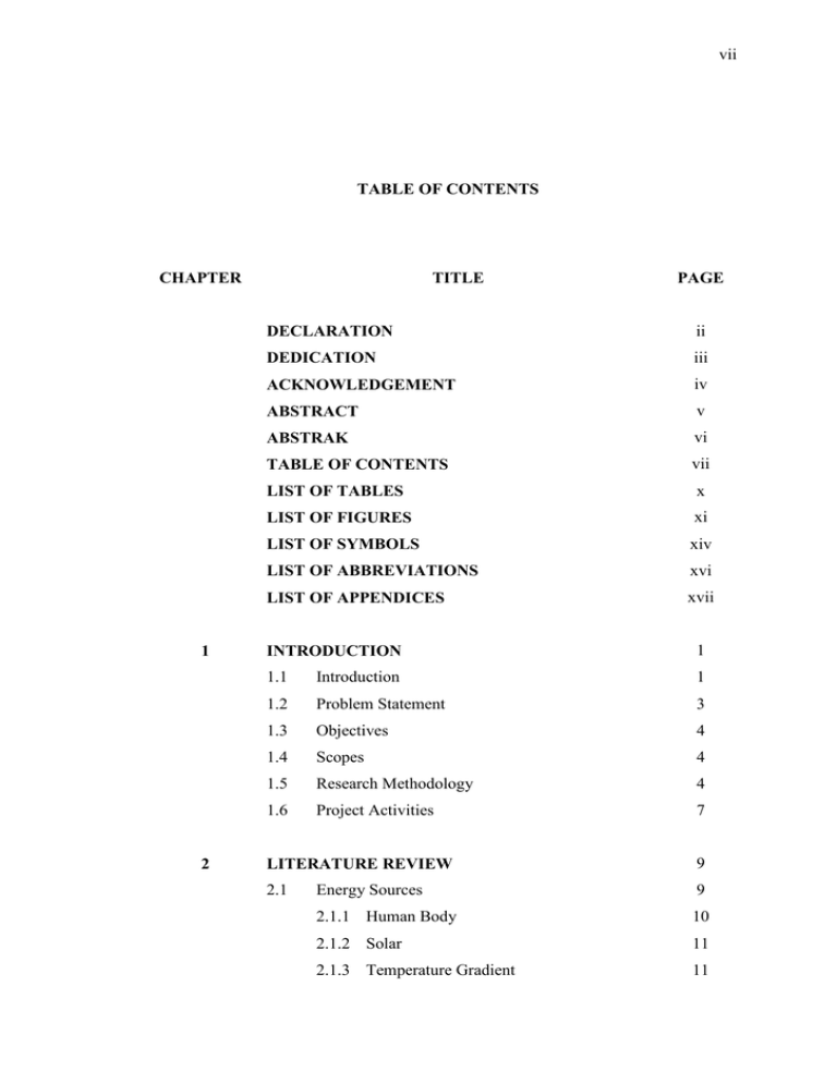
vii TABLE OF CONTENTS CHAPTER 1 2 TITLE PAGE DECLARATION ii DEDICATION iii ACKNOWLEDGEMENT iv ABSTRACT v ABSTRAK vi TABLE OF CONTENTS vii LIST OF TABLES x LIST OF FIGURES xi LIST OF SYMBOLS xiv LIST OF ABBREVIATIONS xvi LIST OF APPENDICES xvii INTRODUCTION 1 1.1 Introduction 1 1.2 Problem Statement 3 1.3 Objectives 4 1.4 Scopes 4 1.5 Research Methodology 4 1.6 Project Activities 7 LITERATURE REVIEW 9 2.1 Energy Sources 9 2.1.1 Human Body 10 2.1.2 Solar 11 2.1.3 Temperature Gradient 11 viii 3 2.1.4 Air Flow 11 2.1.5 Acoustic Noise 13 2.1.6 Vibration 13 2.1.7 Summary of Viable Power Source 14 2.2 Sources of Vibration 14 2.3 Methods of Converting Vibration into Electricity 15 2.3.1 Electromagnetic (Inductive) Conversion 15 2.3.2 Electrostatic (Capacitive) Conversion 19 2.3.3 Piezoelectric Conversion 21 2.3.4 Comparison of Energy Density 24 2.3.5 Summary of Conversion Mechanisms 25 2.4 Piezoelectricity 26 2.5 Vibration Energy Harnessing using Piezoelectric Materials 27 2.6 Energy Storage Devices 30 2.7 Summary 31 METHODOLOGY 33 3.1 Simulation Setup 33 3.1.1 Piezoelectric Sensing Element 33 3.1.2 Harnessing Circuit 34 Data Acquisition System (DAQ) 37 3.2.1 Flow of Information in DAQ 38 Test Equipment 40 3.3.1 Vibrating Mechanical Equipments 40 3.3.2 Piezoelectric Sensor P-876.A12 DuraAct 41 3.3.3 NI Compact-data Acquisition Unit 42 3.2 3.3 3.3.6.1 NI-9234 Module 42 3.3.4 Processor and LabVIEW 43 3.3.5 Harnessing Circuit 44 3.4 Energy Storage Selection 45 3.5 Experimental Setup 46 3.5.1 Experimental Procedure 46 ix 4 RESULTS AND DISCUSSION 48 4.1 Simulation Result 48 4.2 Experimental Result 53 4.2.1 Turbine 53 4.2.1.1 Accumulated Energy 4.2.2 Centrifugal Pump 4.2.2.1 Accumulated Energy 4.3 5 Overall Analysis 55 55 57 57 CONCLUSION AND RECOMMENDATIONS 59 5.1 Conclusion 59 5.2 Recommendations 60 REFERENCES Appendices A - B 61 65 - 66 x LIST OF TABLES TABLE NO. 1.1 TITLE PAGE Comparison of potential energy sources with a fixed level of power generation and a fixed amount of energy storage 2.1 2 Acceleration (m/s2) magnitude and frequency of fundamental vibration mode for various sources (Roundy et al., 2003) 2.2 14 Summary of maximum energy densities for three types of conversion mechanisms (Roundy and Wright, 2004) 24 2.3 Comparison summary of three conversion mechanisms 25 2.4 Comparison of piezoelectric materials (Gonzalez et al., 2002) 27 4.1 Summary of simulation results 53 4.2 Summary of actual experiment results 58 xi LIST OF FIGURES FIGURE NO. TITLE PAGE 1.1 Methodology of the study 6 1.2 Gantt chart for Master Project 1 7 1.3 Gantt chart for Master Project 2 8 2.1 Two approaches to unobtrusive 31-mode piezoelectric energy harnessing in shoes: a PVDF stave under the ball of the foot and a PZT dimorph under the heel (Shenck and Paradiso, 2001) 2.2 10 Schematic and pictures of the fabricated electric energy generator. (a) Schematic showing the arrangement of the bimorph transducers. (b) Photograph of the fabricated prototype. (c) Loading of the bimorphs using rectangular hooks (Chen et al., 2006) 12 2.3 Schematic of overall AEH (Horowitz et al., 2006) 13 2.4 Schematic diagram of linear inertial generator (Williams and Yates, 1996) 2.5 Schematic cross-section of micromachined generator (Williams et al., 2001) 2.6 17 18 Electromagnetic conversion device (Amirtharajah and Chandrakasan, 1998) 18 2.7 In-plane overlap (Roundy et al., 2003) 20 2.8 In-plane gap closing (Roundy et al., 2003) 20 2.9 Out-of-plane gap closing (Roundy et al., 2003) 20 2.10 Illustration of 33 mode and 31 mode operation for piezoelectric material (Roundy et al., 2003) 2.11 Equivalent circuit for a piezoelectric generator 22 xii (Roundy et al., 2003) 2.12 Concept of 23 vibration energy harnessing using piezoelectric materials 2.13 27 Experimental setup showing a Quick Pack QP40N attached to the shaker and dimensions of beam when one end is clamped (Sodano et al., 2004) 28 2.14 Size and layout of the PZT plate (Sodano et al., 2005) 29 2.15 Size and layout of the MFC plate (Sodano et al., 2005) 29 2.16 Size and layout of the Quick Pack actuator (Sodano et al., 2005) 29 3.1 Block diagram for piezoelectric accelerometer 34 3.2 Sensing element of piezoelectric accelerometer developed using Matlab SIMULINK 3.3 Non-adaptive harnessing circuit (Mingjie and WeiHsin, 2005) 3.4 34 35 Non-adaptive harnessing circuit developed using Matlab SIMULINK 36 3.5 Block diagram of data acquisition system 37 3.6 Experimental setup layout 39 3.7 Turbine 40 3.8 Centrifugal pump 41 3.9 Piezoelectric sensor P-876.A12 DuraAct 41 3.10 NI compact-data acquisition unit 42 3.11 NI-9234 module 43 3.12 Processor with LabVIEW software 44 3.13 Harnessing circuit 45 3.14 Capacitor 45 3.15 Experimental setup 46 4.1 Acceleration versus time at different amplitude of (a) 0.05 V pp , (b) 0.10 V pp and (c) 0.15 V pp 4.2 50 Voltage versus time at different amplitude of (a) 0.05 V pp , (b) 0.10 V pp and (c) 0.15 V pp 52 xiii 4.3 Voltage versus time for the turbine at speed of 1150 rpm 4.4 Current versus time for the turbine at speed of 1150 rpm 4.5 56 Current versus time for the centrifugal pump at speed of 1900 rpm 4.12 56 Voltage versus time for the centrifugal pump at speed of 1900 rpm 4.11 56 Current versus time for the centrifugal pump at speed of 1700 rpm 4.10 55 Voltage versus time for the centrifugal pump at speed of 1700 rpm 4.9 54 The amount of voltage accumulated and stored in the capacitor for the turbine at speed of 1450 rpm 4.8 54 Current versus time for the turbine at speed of 1450 rpm 4.7 54 Voltage versus time for the turbine at speed of 1450 rpm 4.6 53 56 The amount of voltage accumulated and stored in the capacitor for the centrifugal pump speed at 1900 rpm 57 xiv LIST OF SYMBOLS °C - Celsius 𝛷𝐵 - Magnetic flux Ω - Ohm 𝛿 - Mechanical strain 𝜀 - Induced emf; Dielectric constant ε0 - Dielectric constant of free space, Permittivity of free space 𝜇0 - Permeability of free space 𝜎 - Mechanical stress 𝜎𝑦 - Yield stress A - Ampere 𝑎 - Acceleration - Magnetic field - Capacitance 𝑐 - Elastic constant 𝐷 - Electrical displacement (charge density) 𝑑 - Gap or distance between plates; Piezoelectric strain coefficient dB - Decibel 𝐸 - Electric field f - Frequency Hz - Hertz I, 𝑖 - Current k - Coupling coefficient; Piezoelectric constant 𝑙 - Length of one coil (2πr); Length of plate m - Meter 𝑁 - Number of turns in coil - Charge on capacitor R - Resistance 𝐵 𝐶 𝑄 xv rpm - Revolution per minute s, sec - Second 𝑡 - Thickness V, Volt - Voltage Vp - Voltage peak V pp - Voltage peak-to-peak W - Watt 𝑤 - Width of plate - Modulus of elasticity (Young’s Modulus) 𝑦 - Distance coil moves through magnetic field 𝑌 xvi LIST OF ABBREVIATIONS A/D - Analog to Digital AC - Alternate Current AI - Analog Input AO - Analog Output AEH - Acoustic Energy Harvester BaTiO 3 - Barium Tinate D/A - Digital to Analog DAQ - Data Acquisition System DC - Direct Current DIO - Digital I/O fpm - feet per minute HVAC - Heating, Ventilation and Air Conditioning I/O - Input to Output IEPE - Integrated Electronic Piezoelectric MFC - Macro-Fiber Composite NI - National Instrumentation PI - Physik Instrumente PVDF - Polyvinylidene Fluoride PZT - Lead Zirconate Tinate PZT-5A - Hard Lead Zirconate Tinate QP - Quick Pack RFID - Radio Frequency Identification xvii LIST OF APPENDICES APPENDIX TITLE A Properties of piezoelectric patch actuator type PAGE DuraAct P-876.A12 (Physik Instrumente (PI) GmbH & Co. KG, 2008) B 64 Technical data of piezoelectric patch actuator type DuraAct (Physik Instrumente (PI) GmbH & Co. KG, 2008) 65


