Troubleshooting Input Drops on ATM Router
Interfaces
Document ID: 8625
Contents
Introduction
Prerequisites
Requirements
Components Used
Conventions
Traditional Reasons for Input Drops
Understanding Throttles
Understanding Flushes
InPktDrops on an ATM VC
Other Reasons for Input Packet Drops
Known Issue: Negative Input Counters
Related Information
Introduction
All types of router interfaces, from serial to Ethernet to ATM, can report a large number of input drops in the
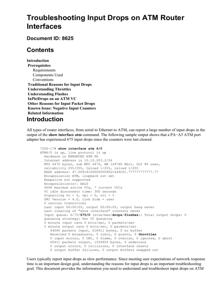
output of the show interface atm command. The following sample output shows that a PA−A3 ATM port
adapter has experienced 675 input drops since the counters were last cleared.
7200−17# show interface atm 4/0
ATM4/0 is up, line protocol is up
Hardware is ENHANCED ATM PA
Internet address is 10.10.203.2/24
MTU 4470 bytes, sub MTU 4470, BW 149760 Kbit, DLY 80 usec,
reliability 255/255, txload 1/255, rxload 1/255
NSAP address: 47.009181000000009021449C01.777777777777.77
Encapsulation ATM, loopback not set
Keepalive not supported
Encapsulation(s): AAL5
4096 maximum active VCs, 7 current VCCs
VC idle disconnect time: 300 seconds
Signalling vc = 5, vpi = 0, vci = 5
UNI Version = 4.0, Link Side = user
0 carrier transitions
Last input 00:00:05, output 00:00:05, output hang never
Last clearing of "show interface" counters never
Input queue: 0/75/675/0 (size/max/drops/flushes); Total output drops: 0
Queueing strategy: Per VC Queueing
5 minute input rate 0 bits/sec, 0 packets/sec
5 minute output rate 0 bits/sec, 0 packets/sec
44060 packets input, 618911 bytes, 0 no buffer
Received 0 broadcasts, 0 runts, 0 giants, 0 throttles
0 input errors, 0 CRC, 0 frame, 0 overrun, 0 ignored, 0 abort
65411 packets output, 1554954 bytes, 0 underruns
0 output errors, 0 collisions, 0 interface resets
0 output buffer failures, 0 output buffers swapped out
Users typically report input drops as slow performance. Since meeting user expectations of network response
time is an important design goal, understanding the reasons for input drops is an important troubleshooting
goal. This document provides the information you need to understand and troubleshoot input drops on ATM
interfaces.
Note: For information on troubleshooting input errors on PA−A3 ATM port adapters, click here.
Prerequisites
Requirements
There are no specific requirements for this document.
Components Used
This document is not restricted to specific software and hardware versions.
Conventions
For more information on document conventions, refer to the Cisco Technical Tips Conventions.
Traditional Reasons for Input Drops
Cisco IOS® Software switching methods define how the router forwards a packet from an ingress (incoming)
interface to an egress (exiting) interface.
The least−preferred method of Cisco IOS Software switching is process switching. In this, the central CPU
performs a complete routing−table lookup based on the destination IP address. Process switching means that
the router cannot use a preferable route−cache method, such as fast switching or Cisco Express Forwarding
(CEF), to handle the forwarding decision. As a result, the router is forced to copy the packet from an
input/output (I/O) buffer in static random−access memory (SRAM), also known as MEMD on 7xxx
platforms, to a system buffer in dynamic random−access memory (DRAM). This is where Cisco IOS
Software code, data structures, and dynamic tables are stored.
On ATM and non−ATM interfaces, the system may count input queue drops if the number of packet buffers
allocated to the interface is exhausted or reaches its maximum threshold. When using a route−cache method,
the system stores a packet in SRAM or packet memory. When using process switching, it stores a packet in
DRAM.
For further information, refer to Troubleshooting Input Queue Drops and Output Queue Drops.
Understanding Throttles
The output of the show interface atm command might display a high number of throttles along with input
queue drops. Input queue drops occur when a packet is being process switched. The throttles counter
increments when a system buffer is available, but the interface already has the maximum number of packets
waiting to be processed in the input hold queue The router temporarily disables the interface to give the
interface time to catch up and process the already enqueued packets.
You can troubleshoot throttles by determining the root cause of why a high number of packets are being
process switched.
Understanding Flushes
The flushes counter in the show interface atm command output increments as part of selective packet discard
(SPD), which implements a selective packet drop policy on the router's IP process queue. Therefore, it applies
to only process switched traffic.
The purpose of SPD is to ensure that important control packets, such as routing updates and keepalives, are
not dropped when the IP input queue is full. When the size of the IP input queue is between the minimum and
maximum thresholds, normal IP packets are dropped based a certain drop probability. These random drops are
called SPD flushes.
In LAN Emulation (LANE) environments, the flush counter increments only for process switched traffic.
LANE is supported by CEF. To troubleshoot incrementing flushes, determine how packets are being IOS
switched by issuing the show ip interface atm command. In addition, confirm that LANE Data Direct VCs
are forming. Capture the output of the show lane client output command.
InPktDrops on an ATM VC
The output of the show atm vc {vcd#} command displays an InPktDrops counter.
7200−1# show atm vc 200
atm6/0: VCD: 200, VPI: 5, VCI: 200
UBR, PeakRate: 44209
AAL5−LLC/SNAP, etype:0x0, Flags: 0xC20, VCmode: 0x0
OAM frequency: 0 second(s)
InARP DISABLED
Transmit priority 4
InPkts: 0, OutPkts: 0, InBytes: 0, OutBytes: 0
InPRoc: 0, OutPRoc: 0, Broadcasts: 0
InFast: 0, OutFast: 0, InAS: 0, OutAS: 0
InPktDrops: 157, OutPktDrops: 0
CrcErrors: 0, SarTimeOuts: 0, OverSizedSDUs: 0
OAM cells received: 0
OAM cells sent: 0
Status: UP
While input queue drops on an interface point to a high number of process switched packets, a non−zero value
for the InPktDrops of a VC counter suggests that the ATM interface is running out of packet buffers for an
individual virtual circuit (VC), or is exceeding the total number of VC buffers that can be shared by the VCs.
For the PA−A3, such drops occur as a result of the PA−A3 driver implementing one of two throttling
mechanisms:
1. The PA−A3 places a quota on the number of packet buffers that a VC can use from the receive
segmentation and reassembly (SAR) common pool. This quota equates to a "receive credits" value
which varies based on the configured traffic shaping rate. In addition, it prevents one aggressive or
overloaded VC from exhausting all buffer resources. When the PA−A3 driver receives a packet and
forwards it to either the processor or to an egress interface, it deducts one buffer credit. It restores a
credit when either the processor or the egress interface returns the packet buffer to the VC's pool. If
the VC experiences congestion and runs out of credits, the PA−A3 must drop subsequent packets and
increments the InPktDrops counter.
2. The PA−A3 throttles an ATM VC when the adapter itself runs out of packet buffers. On an ATM
interface with a large number of congested VCs, the adapter can run out of packet buffers quite easily
since the per−VC quotas overlap and are not exclusive. In other words, the total number of buffers
specified in the per−VC quotas exceeds the total number of buffers actually available on the PA−A3.
When all of the PA−A3's buffers are in use, the framer's FIFO queue hold incoming cells. These can
lead to overruns if congestion persists. Once such a backpressure condition occurs, the framer FIFO
may drop cells, causing cyclic redundancy check (CRC) errors.
InPktDrops counts the number of times a packet was dropped before it reached the host interface. Packets are
not registered in the interface statistics until the host interface receives it from the SAR buffer. Thus, you may
see drops with the show atm vc command, but see few, if any, drops with the show interface atm command.
The show controllers atm command displays three useful counters for determining whether the ATM
interface is running out of onboard reassembly buffers. These are highlighted in bold below.
Note: The Rx_count should be well below the Rx_threshold.
C7200# show controller atm 1/0
Interface atm1/0 is up
Hardware is ENHANCED ATM PA − SONET OC3 (155Mbps)
dfs is enabled, hwidb−>ip_routecache = 0x15
lane client mac address is 0060.3e73.e640 active HSRP group:
Framer is PMC PM5346 S/UNI−155−LITE, SAR is LSI ATMIZER II
!−−− Output suppressed.
Control data:
Rx_max_spins=2, max_tx_count=17, TX_count=4
Rx_threshold=1366, Rx _count=15, TX_threshold=4608
TX bfd write indx=0x11, Rx _pool_info=0x6066A3E0
!−−− Output suppressed.
Counter
Explanation
Maximum number of receive particles that
the PA−A3 driver or egress port adapter can
hold without regulating receive particle
usage among the configured VCs. To prevent
any VC from allocating too many packet
buffers and inhibiting other VCs from
receiving packets, the PA−A3 uses a receive
packet buffer regulating mechanism. When
Rx_threshold
the total number of receive particles held by
the PA−A3 driver or the egress interface
exceeds this threshold, the next packet
received by the PA−A3 is checked to see if
one VC occupies too many packet buffers. If
so, the PA−A3 discards incoming packets
until the total number of receive particles
held by this violating VC falls below the
quota.
Internally, the PA−A3 microcode notifies the
PA−A3 driver of the arrival of incoming
packets by asserting receive interrupts. The
PA−A3 driver catches the receive interrupt
Rx_max_spins
and then drains as many particles from the
receive ring as it can. This counter records
the maximum number of receive particles
ever drained by the PA−A3 driver in a single
interrupt.
Rx_count
Total number of receive or reassembly
particles currently held by the driver.
Other Reasons for Input Packet Drops
In addition to exceeding a VC's reassembly buffer credit, an ATM interface may drop packets because:
• No route to destination prefix
• Incomplete ARP entry
• Configured policy of an ACL
In certain versions of Cisco IOS Software, the PA−A3 driver is counting these drops as VC input packet drops
and incrementing the per−VC InPktDrop counter. This problem is cosmetic only and has no performance
impact. It is resolved via bug ID CSCdu23066 for the PA−A3−OC3/T3 and via bug ID CSCdw78297 for the
PA−A3−OC12.
Known Issue: Negative Input Counters
Cisco DDTS CSCdm54053 resolves a problem in which the output of show interface displays negative packet
input and output counters on a subinterface. A fix is implemented in various versions of Cisco IOS Software
Version 12.0(6) as well as 12.0(7)XE2.
Related Information
• How to Verify Cisco Express Forwarding Switching
• Troubleshooting Input Queue Drops and Output Queue Drops
• Troubleshooting Output Drops on ATM Router Interfaces
• ATM Technology Support
• Cisco ATM Port Adapter
• Technical Support − Cisco Systems
Contacts & Feedback | Help | Site Map
© 2014 − 2015 Cisco Systems, Inc. All rights reserved. Terms & Conditions | Privacy Statement | Cookie Policy | Trademarks of
Cisco Systems, Inc.
Updated: Nov 15, 2007
Document ID: 8625


