COMBINATION RADIAL-AXIAL MAGNETIC BEARING
advertisement
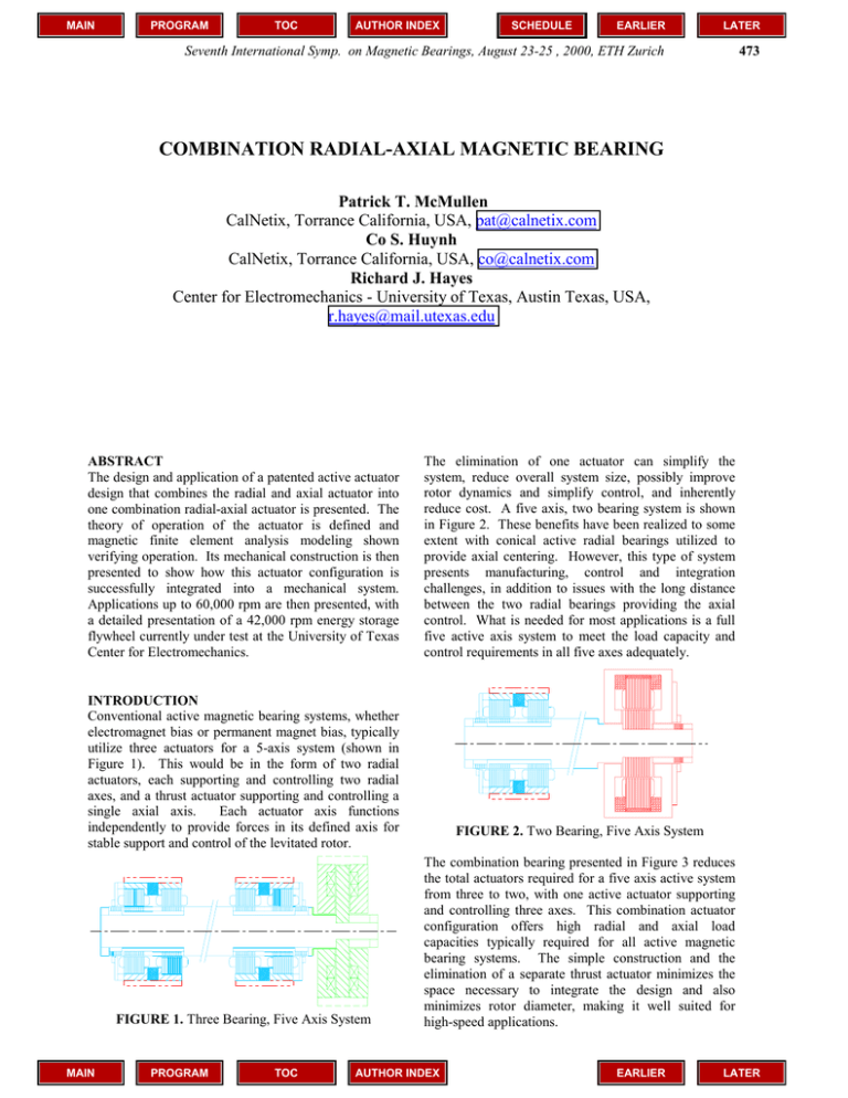
MAIN PROGRAM TOC AUTHOR INDEX SCHEDULE EARLIER LATER Seventh International Symp. on Magnetic Bearings, August 23-25 , 2000, ETH Zurich 473 COMBINATION RADIAL-AXIAL MAGNETIC BEARING Patrick T. McMullen CalNetix, Torrance California, USA, pat@calnetix.com Co S. Huynh CalNetix, Torrance California, USA, co@calnetix.com Richard J. Hayes Center for Electromechanics - University of Texas, Austin Texas, USA, r.hayes@mail.utexas.edu ABSTRACT The design and application of a patented active actuator design that combines the radial and axial actuator into one combination radial-axial actuator is presented. The theory of operation of the actuator is defined and magnetic finite element analysis modeling shown verifying operation. Its mechanical construction is then presented to show how this actuator configuration is successfully integrated into a mechanical system. Applications up to 60,000 rpm are then presented, with a detailed presentation of a 42,000 rpm energy storage flywheel currently under test at the University of Texas Center for Electromechanics. The elimination of one actuator can simplify the system, reduce overall system size, possibly improve rotor dynamics and simplify control, and inherently reduce cost. A five axis, two bearing system is shown in Figure 2. These benefits have been realized to some extent with conical active radial bearings utilized to provide axial centering. However, this type of system presents manufacturing, control and integration challenges, in addition to issues with the long distance between the two radial bearings providing the axial control. What is needed for most applications is a full five active axis system to meet the load capacity and control requirements in all five axes adequately. INTRODUCTION Conventional active magnetic bearing systems, whether electromagnet bias or permanent magnet bias, typically utilize three actuators for a 5-axis system (shown in Figure 1). This would be in the form of two radial actuators, each supporting and controlling two radial axes, and a thrust actuator supporting and controlling a single axial axis. Each actuator axis functions independently to provide forces in its defined axis for stable support and control of the levitated rotor. FIGURE 1. Three Bearing, Five Axis System MAIN PROGRAM TOC FIGURE 2. Two Bearing, Five Axis System The combination bearing presented in Figure 3 reduces the total actuators required for a five axis active system from three to two, with one active actuator supporting and controlling three axes. This combination actuator configuration offers high radial and axial load capacities typically required for all active magnetic bearing systems. The simple construction and the elimination of a separate thrust actuator minimizes the space necessary to integrate the design and also minimizes rotor diameter, making it well suited for high-speed applications. AUTHOR INDEX EARLIER LATER MAIN PROGRAM TOC AUTHOR INDEX EARLIER LATER COMPONENT AND SYSTEM DESIGN 474 Axial Control Coil Axial Air Gap Permanent Magnet Pole Piece Radial Control Coil Radial Air Gap FIGURE 4. Key Components of the Combination Radial/Thrust Permanent Magnet Bias Bearing FIGURE 3. Three Dimensional View of Combination Bearing MAGNETIC DESIGN This novel bearing design is constructed in a homopolar configuration such that the bias field is one polarity on all the radial poles, and the opposite polarity on the axial poles (i.e. the bias field enters the rotor through the radial air gaps and exits the rotor through the axial air gaps). This eliminates field polarity changes in the radial air gap to minimize rotor losses [1,2]. The design utilizes a permanent magnet or electromagnet to provide both radial and axial bias fields. The permanent magnet provides the linear negative stiffness benefit as present in the radial homopolar magnetic bearing [3]. Control coils for each radial axis and the axial axis act independently to modulate forces in each of the independent axes. The control field boosts the bias field in the direction of added force, and bucks the bias in the opposite pole. This difference in opposite pole fields provides the net force in the direction desired. The combination radial/thrust bearing utilizes a single radially polarized permanent-magnet ring to energize the radial and axial magnetic air gaps. The packaging of the control coils and ferromagnetic pole pieces results in virtually all of the volume being utilized functionally, leaving very little unused space within the confines of the bearing module. This highly efficient use of volume results in maximum spatial, magnetic, and electrical efficiencies. Figure 4 identifies the primary components of the bearing. MAIN PROGRAM TOC The radially polarized permanent magnet ring is nested between an outer cylindrical iron pole piece and an inner electrical steel laminated stator assembly. The permanent magnet creates a magnetic flux (identified as ØPM) in the axial air gaps between each end of the thrust rotor and the pole piece, and also creates a flux in the radial air gaps of the four salient poles of the laminated stator assembly. This path is presented in Figure 5. This approach utilizes a single permanent magnet that energizes both axial and radial gaps in a spatially efficient manner with minimum iron path lengths. The bias flux density can be adjusted for the radial and axial gaps to meet bearing operating requirements. This is shown in Figure 6 in a magnetic finite element model result shows the effective bias flux density in the radial and axial air gaps. As this is a twodimensional model, the radial actuator stator was split in the center to account for the effective slot area, while still providing effective leakage flux modeling. AUTHOR INDEX FIGURE 5. Axial Flux Path EARLIER LATER MAIN PROGRAM TOC AUTHOR INDEX EARLIER LATER Seventh International Symp. on Magnetic Bearings, August 23-25 , 2000, ETH Zurich 475 Axial Gap Radial Gap Axial Gap density distribution in the combination bearing with the control coil operating at its full rated MMF. As seen the flux density in the lower pole is near maximum, and the flux density at the upper pole in near minimum, thus producing maximum for from the thrust axis of the bearing. FIGURE 6. Bias Flux Density in Combination Bearing Air Gaps An active closed-loop servo control system is, of course, required to maintain equal air gaps in the radial and thrust axes, because the permanent-magnet force bias field is statically unstable. Control forces for the axial axis are produced by energizing two small coaxial coils nested inside the outer cylindrical pole piece. These coils are energized with like polarities so that they create electromagnetic thrust control flux (∅TEM) that adds to the permanent magnet flux (∅PM) in one of the axial air gaps and decreases the flux in the opposite gap, shown in Figure 5. This creates an axial force imbalance between the fixed outer cylindrical pole piece and the thrust rotor. In modeling the axial control flux, the reluctance of the path must include the cross lamination reluctance in the rotor to arrive at an accurate prediction of control MMF. Simplified by not including leakage reluctance, this path reluctance would be represented as follows: RPATH=RCORE+2xRPOLE+2xRGAP+RROTOR Where, RPATH is the total axial path reluctance RCORE is the iron core reluctance RPOLE is the reluctance of each iron thrust pole RGAP is the reluctance of each axial air gap, and RROTOR is the rotor axial path reluctance, including cross lamination effects This, and associated fringing and leakage factors determined by the geometry of the bearing, are used to determine the MMF required for of the axial control coils. It is important to note in the reluctance modeling for the axial control flux, as well as see in the radial control flux, that the permanent magnet reluctance does not need to be included in this determination. As seen in the control flux paths, the control flux is not required to go though the high reluctance magnet. This minimizes the MMF required by the control flux and the coil effective area. The result of the axial control and permanent magnet field can be seen in Figure 7. This figure presents a two dimensions model of flux MAIN PROGRAM TOC FIGURE 7. Flux Density Plot in 2-D Magnetic Analysis Model with Control MMF at 100% Radial control forces are produced by energizing coil pairs on the laminated stator salient poles. Coil pairs are located 180 degrees apart and are operated in concert so as to generate an electromagnetic flux (∅REM) that adds to the permanent magnet flux of the radial air gap on one side of the shaft and subtracts from the flux of the air gap on the opposite side of the shaft, as shown in Figure 8. This creates a net radial force between the fixed stator assembly and the rotating shaft target. Figure 9 presents a three-dimensional flux plot of the combination bearing with the control coils in one of the radial axes operating to increase flux in one radial pole, and reduce flux density in the opposite radial pole. As seen, the other non-active radial axis air gaps remain uniform and produce no force, which would result in cross coupling. Figure 10 presents an axial cross section with the radial coils operating, showing the axial air gap uniformity when the radial control is in operation. This lack of cross-coupling between radial and thrust axes has been seen in tested units, confirming the model results. AUTHOR INDEX FIGURE 8. Radial Control and Bias Flux Paths EARLIER LATER MAIN PROGRAM TOC AUTHOR INDEX EARLIER LATER COMPONENT AND SYSTEM DESIGN 476 actuator center, important for alignment tolerance of magnetic bearing center to touchdown bearing center. FIGURE 9. Radial Control Flux Density Plot FIGURE 11. Exploded View of Combination Bearing Components FIGURE 10. Flux Density Plot Through Axial Section when Radial Control Operating With the sharing of the permanent magnet field at the same operating flux densities, the peak radial load capacity per radial axis will be 50% of the peak axial load capacity. This relationship in radial to axial load, derived from the pole areas, is the typical load relationship for most combination bearing designs produced to date. Variations in this relationship can be achieved by operating the radial and axial air gaps at different bias levels. This is typically done when load is larger in one primary axis than the other, reducing overall size. This case though does not result in the optimal configuration to maximize the total load in all axes the actuator can supply. MECHANICAL CONSTRUCTION While the actuator is designed for providing three axes of control, its basic construction allows for easy design integration and assembly into a system. Key components shown exploded in Figure 11 (permanent magnet, radial stator winding, thrust coils, and the outboard thrust pole) are all pre-assembled and aligned as components, simplifying final assembly to rotor assembly, inboard thrust pole, and stator assembly. The two stator components prior to assembly are shown in Figure 12. The radial stator assembly is fit into the magnet ring and outer pole piece, and aligned to be concentric with the outer pole diameter. This provides alignment between the housing bore and the radial MAIN PROGRAM TOC FIGURE 12. Two Piece Stator Prior to Assembly (Inboard Thrust Pole is Split for Assembly) The rotor assembly is first assembled onto the rotor shaft, typically with an interference fit to maintain contact with the shaft during all speed and operating conditions. Once assembled and finish ground, it does not need to be removed. This one-time rotor assembly greatly simplifies construction and durability of the system. Its small diameter also minimizes rotating stresses for high operating speeds. The inboard side stator pole, split in two to four pieces for assembly, is then mounted to the housing over the rotor on the inboard side. The remaining stator assembly, consisting of the wound radial stator, permanent magnet, and the outboard thrust pole, is then installed into the housing to complete assembly. APPLICATION TESTING This combination bearing configuration has been fabricated and operated in a number of applications, including a 42,000 rpm flywheel (discussed in detail in the next section), a 45,000 rpm air conditioning compressor, a 42,000 rpm turbomolecular pump, and a 60,000 rpm flywheel. The configuration is also undergoing testing to 60,000 rpm in an aircraft air cycle AUTHOR INDEX EARLIER LATER PROGRAM TOC AUTHOR INDEX EARLIER LATER Seventh International Symp. on Magnetic Bearings, August 23-25 , 2000, ETH Zurich 477 compressor application. The size of each actuator was unique for each application, designed for optimum integration into the system. Load capacity varied from 90/400 N (radial/axial) to 1,112/2,224 N (radial/axial). Application load conditions typically have a static weight or thrust load on the axial axis, at 40% to 50% of the peak axial load capacity, and a small static radial load (20% of the peak load capacity) combined with dynamic loads due to high speed operation. Key Application: High Speed Flywheel on a Transit Bus Application The University of Texas Center for Electromechanics, and its industrial partners, CalNetix, AlliedSignal Aerospace and Avcon Inc., have developed and tested a high performance flywheel battery (FWB) for power averaging on a 12,725 kg. (28,000 lb.) hybrid electric transit bus [4]. The system incorporates a high speed (40,000 RPM) 150 kW permanent magnet motor generator and magnetic bearings (designed by Avcon and commissioned by CalNetix) to levitate a 2kWhr composite flywheel, shown in Figure 13. FIGURE 13. Flywheel System with Combination (Combo) Bearing Beyond the basic power and energy requirements, the transit bus application imposes additional environmental conditions that impact system design. These include an ambient temperature range in the engine compartment of -40°C (-40°F) to 63°C (145°F) and frequent shock and vibration loads of 1.0G to 2.0G with occasional loads exceeding 8G. Controlling the 135 pound rotor in its operating range of 30,000 to 40,000 RPM under normal loads (up to 3G) is accomplished with the magnetic bearings while backup bearings are incorporated for loads exceeding 3G. This goal of maximizing energy density leads to carbon fiber composites as the material of choice for modern high performance flywheels. These materials are capable of operating safely at surface speeds (on the outer diameter) of approximately 1,000 m/s, which MAIN PROGRAM TOC results in unacceptable windage losses unless the flywheel operates in a vacuum. This means that heat removal from the FWB rotor must be accomplished via radiation, severely limiting rotor cooling. Consequently heat generation on the FWB rotor becomes a major “design driver”. To minimize rotor heating UT-CEM chose to use low loss homopolar permanent magnet bias magnetic bearings and a permanent magnet motor generator. For both of these components, most heat generation is in the stator windings, which can be located outside the vacuum and actively cooled, as in the case of the motor generator, or cooled by simple conduction as in the case of the magnetic bearings. Bearing Design. The magnetic bearings are designed to accommodate rotor static loads plus an additional 3G of dynamic loading under all normal operating conditions (from 0-40,000 RPM). The “combo” bearing, which must produce both radial and thrust force simultaneously, is designed to deliver approximately 250 pounds of radial force and 500 pounds of thrust force. Because the system is vertically mounted (to reduce gyroscopic loads) the thrust bearing is designed to carry the rotor weight at all times plus have the reserve capacity to accommodate a 3G bump [5]. In operation the magnetic bearings allow the flywheel rotor to rotate about its “mass center” as opposed to its geometric center (much like a conventional bearing on dampers) minimizing loads on the transmitted to ground. To eliminate any unwanted motion of the bearing components during operation both the rotor and stator components are mounted using interference fits. Combination Bearing Testing. Prior to delivery to UT-CEM the magnetic bearing system was tested both statically and dynamically for stable operation up to 5,000 RPM on a “dummy” all steel rotor. Peak load test results are presented in Table 1 with the system data. Negative stiffness test data, presented in Figure 14, shows the linearity of the negative stiffness in the working air gap, and the roughly 2x relationship between thrust and radial axes. AUTHOR INDEX 1200 Negative Stiffness Force, N MAIN 1000 Thrust Axis 800 600 Radial Axis 400 200 0 0 0.05 0.1 0.15 0.2 0.25 Gap Position, mm FIGURE 14. Load Test Results EARLIER LATER MAIN PROGRAM TOC AUTHOR INDEX LATER COMPONENT AND SYSTEM DESIGN 478 Dynamic testing to determine bandwidth of each axis was performed for the combination bearing radial and thrust axes. Figure 15 presents these test results for axis gain and phase. As expected, the axial axis has significantly lower dynamic response as drive frequency increases. This effect is typical for axial bearings due to the primarily solid iron flux path, whereas radial bearings utilize a laminated iron flux path to maximize their dynamic response. FIGURE 15. Combination Bearing Dynamic Response for the Radial (X1) and Axial (Z) Axes System Testing Results. All of the system level tests of the FWB have been conducted with a 0.8 kwhr titanium flywheel prior to retrofitting of the 2.0 kwhr composite flywheel. The tests have been very successful and the system is operating as designed [6]. Specific test data is summarized in Table 1. While not all of the long term testing has been completed at this date, no inherent technical limitations with the combination bearing design have been identified that will prevent meeting all of the original design goals. TABLE 1. System Test Summary Design Parameter Design Goal Verified 2 2 110 60 150 135 580 605 1,110 1,080 2,225 2,430 Verified during static testing 42,000 42,000 Verified by full system testing 40,000 37,000/ 32,000 Bump/full drop Energy stored (kWh) Continuous power (kW) Peak power (kW) Radial bearing capacity (N) Combo bearing radial capacity (N) Combo bearing thrust capacity (N) Bearing operation speed (rpm) Backup bearing operation (rpm) MAIN EARLIER PROGRAM TOC Notes During spin testing of composite flywheel Continuous power testing not completed Full power testing not completed Verified during static testing Verified during static testing The combination bearing has met all required performance criteria for flywheel testing to date. Near term plans of the 0.8 kWhr titanium flywheel will focus on operating the flywheel under conditions similar to what it would see on the bus over an eight or sixteen hour day. Following that testing, the 2.0 kWhr composite flywheel will be retrofit onto the rotor for testing, and then the system will be integrated into a gimbal mount and skid designed for integration with the transit bus. The skid will then be mounted on a terrain tester at UT-CEM to simulate the bus motion and G loading that will be seen during operation on the transit bus. After the system is proven on the terrain tester it will be installed on the transit bus for fieldtesting. Bearing performance will be assessed through all system testing. CONCLUSION The overall reduction in system size and weight, and potential cost reduction make this type of bearing desirable in many applications. The actuator has demonstrated performance in a number of applications requiring high radial load bandwidth and high static axial load support, both at the same time. The unique advantages this actuator offers a system expand the application of magnetic bearings to size and weight critical systems. A number of configurations for this design beyond the ones delivered as of this writing will offer these significant advantages to even larger systems. REFERENCES 1. Meeks, C.R., DiRusso, E., Brown, G.V. , 1990, “Development of a Compact, Light Weight Magnetic Bearing”, AIAA/SAE/ASME/ASEE 26th Joint Propulsion Conference, Orlando. 2. Allaire, P., Kasarda, M., Maslen, E., Gillis, G., 1996, “Rotor Power Loss Measurements for Heteropolar and Homopolar Magnetic Bearings”, 5th Int. Symp. on Magnetic Bearings, Virginia. 3. Hawkins, L. A., 1997, "Shock Analysis for a Homopolar, Permanent Magnet Bias Magnetic Bearing System", 97-GT-230, ASME Int. Turbine and Aerospace Congress and Exp., Orlando. 4. Hayes, R.J., Kajs, J.P., Thompson, R.C., Beno, J.H., 1998, “Design and Testing of a Flywheel Battery for a Transit Bus”, SAE 1999-01-1159. 5. Murphy, B.T., Beno, J.H., Bresie, D.A. , 1997, “Bearing Loads in a Vehicular Flywheel Battery”, PR-224, SAE Int. Congress and Exp., Detroit. 6. Hawkins, L.A., Murphy, B.T., Kajs, J.P., 1999, “Application of Permanent Magnet Bias Magnetic Bearings to an Energy Storage Flywheel”, 5th Symp. on Magnetic Suspension Technology, Santa Barbara. AUTHOR INDEX EARLIER LATER
