Modeling and Simulation of Microwave Heating
advertisement
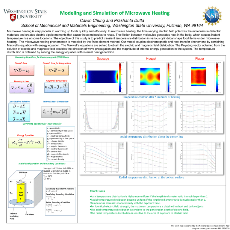
Modeling and Simulation of Microwave Heating Calvin Chung and Prashanta Dutta School of Mechanical and Materials Engineering, Washington State University, Pullman, WA 99164 Microwave heating is very popular in warming up foods quickly and efficiently. In microwave heating, the time-varying electric field polarizes the molecules in dielectric materials and creates electric dipole moments that cause these molecules to rotate. The friction between molecules generates heat in the body, which causes instant temperature rise at some locations. The objective of this study is to predict transient temperature distribution in various cylindrical shape food items under microwave heating. The microwave heating phenomenon is modeled by the finite element method. Our model couples electromagnetic and heat transfer phenomena by combining Maxwell’s equation with energy equation. The Maxwell’s equations are solved to obtain the electric and magnetic field distribution. The Poynting vector obtained from the solution of electric and magnetic field provides the direction of wave propagation and the magnitude of internal energy generation in the system. The temperature distribution is obtained by solving the energy equation with internal heat generation. Governing Equations for Electromagnetic(EM) Waves Gauss’s Law Gauss’s Law for Magnetism D B 0 Faraday’s Law Ampere’s Circuit Law B E t Sausage Nugget Platter D H J t Temperature contour after 5 minutes of heating D E B H J E Constitutive Relation Internal Heat Generation 1 Q v 0 E 2 2 Governing Equation for Heat Transfer Energy Equation T 2 C p k T Q v t – permittivity 0 – permittivity in free space – permeability – electrical conductivity 0 – permeability in free space v – charge density – dielectric loss – angular frequency D – electric flux density E – electric field – magnetic flux density B H – magnetic flux J – current density Axial temperature distribution along the center line Initial Configuration and Boundary Conditions Sausage: L=0.1524 m; d=0.0254 m Nugget: L=0.018 m; d=0.018 m Platter: L= 0.018 m; d=0.08 m Text= 25°C T0= 25°C EM Wave Air d 1 T0 Text Raw Beef Continuity Boundary Condition L n1 E1 n2 E2 Insulating Boundary Condition T ( z, r , t ) 0 z z 0 2 Robin Boundary Condition T ( z, r , t ) h(T Text ) z zL Thermal Insulating Plate Radial temperature distribution at the bottom surface T ( z, r , t ) h(T Text ) r r d /2 EM Wave Conclusions Axial temperature distribution is highly non-uniform if the length to diameter ratio is much larger than 1. Radial temperature distribution become uniform if the length to diameter ratio is much smaller than 1. Temperature increases monotonically with the exposure time. For identical electric field strength, the maximum temperature is obtained in short and bulky objects. The axial temperature distribution is sensitive to the penetration depth of electric field. The radial temperature distribution is sensitive to the area of exposure to electric field. This work was supported by the National Science Foundation’s REU program under grant number EEC 0754370
