Light is a transverse wave: the electric and magnetic fields... perpendicular to the direction of wave motion. The simplest kind... Polarization
advertisement
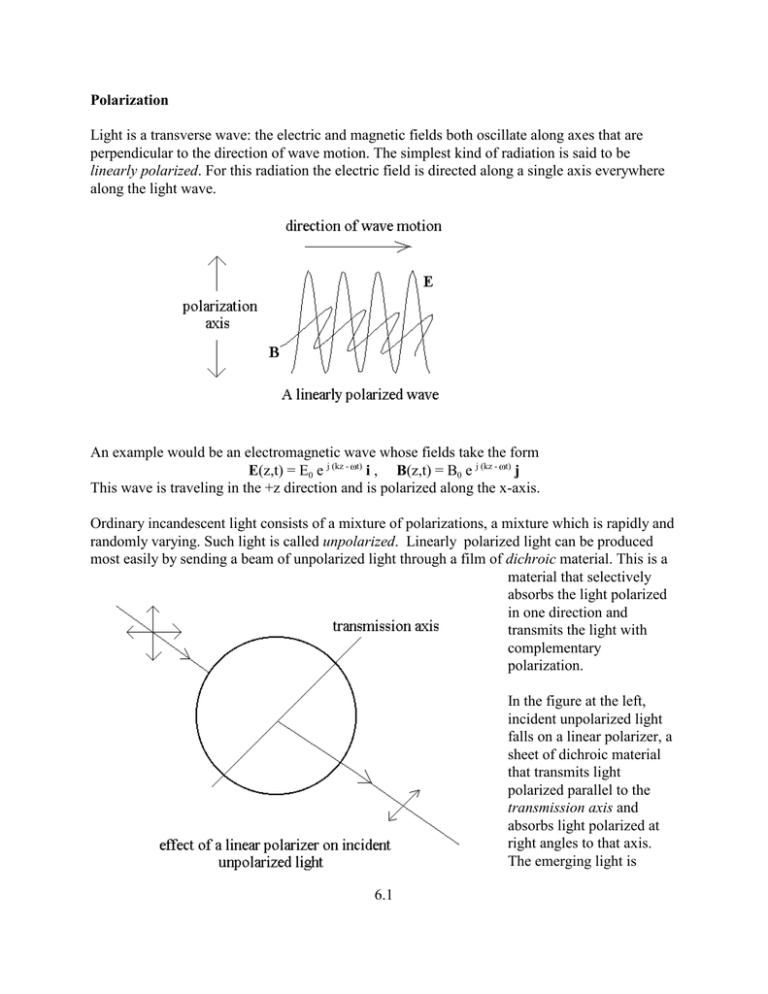
Polarization Light is a transverse wave: the electric and magnetic fields both oscillate along axes that are perpendicular to the direction of wave motion. The simplest kind of radiation is said to be linearly polarized. For this radiation the electric field is directed along a single axis everywhere along the light wave. An example would be an electromagnetic wave whose fields take the form E(z,t) = E0 e j (kz - t) i , B(z,t) = B0 e j (kz - t) j This wave is traveling in the +z direction and is polarized along the x-axis. Ordinary incandescent light consists of a mixture of polarizations, a mixture which is rapidly and randomly varying. Such light is called unpolarized. Linearly polarized light can be produced most easily by sending a beam of unpolarized light through a film of dichroic material. This is a material that selectively absorbs the light polarized in one direction and transmits the light with complementary polarization. In the figure at the left, incident unpolarized light falls on a linear polarizer, a sheet of dichroic material that transmits light polarized parallel to the transmission axis and absorbs light polarized at right angles to that axis. The emerging light is 6.1 linearly polarized with polarization axis parallel to the transmission axis of the polarizer. When polarized light falls on a linear polarizing sheet, only the component of the incident light polarized parallel to the transmission axis is transmitted while the perpendicular component is absorbed. This means that if E0 is the amplitude of the incident light and the angle between the polarization axis of the light and the transmission axis of the polarizer, the amplitude of the transmitted light is E0 cos . Since the intensity is proportional to the square of the amplitude, the transmitted intensity is related to the incident intensity by (13.1) I = I0 cos2 . This relationship is called the law of Malus and holds only for incident linearly polarized light. Dichroism is not difficult to understand Common dichroic materials are formed from long chain-like molecules with electrons that can roam over the length of the molecule. A linearly polarizing sheet has these molecules preferentially oriented in one particular direction in the plane of the sheet, as in the sketch at the left. When a light wave passes through the sheet, the component of the electric field that is parallel to the molecular axis will cause electrons to oscillate back and forth along the length of the molecule, thereby transferring some of the light wave’s energy to electron motion. This electronic motion is resisted by friction with the molecule and its environment and the electrons’ energy will eventually be lost to heat. In this way, the component of electric field parallel to the molecule’s long axis is absorbed. Light polarized oppositely to the long axis of the molecule cannot cause significant electron motion and so is not absorbed. For the case illustrated, the vertical axis would be the 6.2 transmission axis. The law of Malus tells us about how a linear polarizer affects unpolarized light. The electric field of an unpolarized light wave moving in the z direction can be written as (13.2) E = E0 ( cos (t) i + sin (t) j ) sin(k z - t + (t)) \where and are a rapidly and randomly varying functions of time. The fluctuations occur on a time scale of 10-13 s or less and it is usually appropriate to deal with the averaged intensity. The average intensity of this wave is (13.3) I0 = 0 c E0 2 [sin2 (t) + cos2 (t)] sin2 (kz - t + (t)) = 0 c E0 2 sin2 (kz - t+ (t)) = 0 c E0 2 / 2 If the transmission axis of a polarizer lies along the y-direction, the transmitted electric field is (13.3) E = E0 sin (t) sin(k z - t + (t)) j so that the instantaneous transmitted intensity is I(t) = 0 c E0 2 sin2 (t) sin2 (k z - t + (t)). The polarization and phase fluctuations are usually statistically independent. The phase fluctuations arise from atomic collisions while the polarization fluctuations come from different atoms contributing to the radiation, each with a different polarization. We are therefore justified in taking the averages separately: (13.4) I = 0 c E0 2 sin2 (t) sin2 (k z - t + (t)) = so that finally (13.5) I = I0 / 2 which holds for unpolarized light moving through a linear polarizer. 6.3 0 c E0 2 /4 Experiment 6.1: The Law of Malus Apparatus: Two polarizers, one of which is adjustable and equipped with a protractor; table lamp; pc spectrometer. Procedure: Put the table lamp’s light through one polarizer and look at this light through the second adjustable polarizer. Try to line up the transmission axis (TA) of this polarizer so that the transmitted intensity is a maximum. Then place the spectrometer’s fiber-probe on a fixed support so that it is receiving the light through both polarizers. Set the integration time and averaging width for optimum data collection. Fine adjust the TA so that the intensity received by the probe is a maximum. Choose three wavelengths that collectively span most of the visible spectrum and record the intensity at the three selected wavelengths. Then rotate the TA by 10( and repeat the measurements. Continue in 10( increments until the intensity is almost zero. Make a table of your data (in MAPLE). Subtract the dark reading from all entries. Note: This may differ for each wavelength. For each wavelength, plot the intenisty and angle using pointsplot where is the angle between the TA and its position at maximum intensity. On the same graph plot I0cos2 where I0 is the maximum intensity. You will have three graphs that collectively contain all your data as well as the angular distribution predicted by the law of Malus. Comment on how well this law describes the data. 6.4 Experiment 6.2: Quarter and Half Wave Plates Apparatus: Polarizers, two quarter wave plates ( /4 plates) , mercury vapor lamp with green filter, table light. Procedure: 1.Using the green mercury light, cross the polarizer and analyzer (i.e. adjust the TA’s so that no light is transmitted by the analyzer). Place a quarter wave plate between the polarizer and analyzer. Rotate the plate and describe what happens. 2. Remove the polarizer and study the light coming through the /4 plate and the analyzer. Then do the same using only the /4 plate and the polarizer. Can you explain what the /4 plate is doing in terms of dichroism? 3. Next set up the crossed polarizer and analyzer and place two /4 plates between them. Adjust various angles and describe what you see. Question: Can you think of a model to describe this behavior? 6.5 Circular and Elliptic Polarization Linear polarization is not the only way a light wave can be polarized. Consider the following electric field: (13.6) E = E0 [-j i + j] e j (k z - t) whose real part is E0 [sin(k z - t ) i + cos(k z - t) j ] This describes a wave moving in the +z-direction but the phase of the x-component of the radiation differs by 90( from that of the y-component. Examine this wave at the location z=0. At time t=0, the electric field points along the +y axis. When t = T/4 (where T = period = 2 / ), the electric field points along the -x-direction. At t = T/2, it points along the -y direction and at t = 3T/4 it points along the +x direction. At the fixed location z = 0 the electric field appears to rotate counterclockwise. Problem 1: Show that at a fixed time the electric field rotates clockwise with increasing z. A wave like that of (13.6) is said to be left circular polarized (LCP). At a fixed location in space, if one looks into the oncoming wave and points the thumb of the left hand into the wave (opposite to the direction of wave motion), the fingers curl in the sense of rotation of the electric field. In the opposite case, where the electric field rotates in the sense in which the fingers of the right hand curl, we speak of right circular polarization (RCP). Problem 2: Find whether the below electric fields correspond to LCP, RCP, or linear polarization. A. E = E0 [-j i - j ]e j (k z - t) B. E = E0 [ i -j j ] e j (k z - t) C. E = -j E0 [ i + j ] e j (k z - t) D. E = E0 [e j / 4 i + e 3 j / 4 j ] e j (k z - t) 6.6 Problem 3: Find an expression for an electric field of a RCP wave moving in the -x direction. (There is more than one correct answer). A more general kind of polarization corresponds to rotating electric fields with different amplitudes along different axes. As an example, consider the wave whose electric field is (13.7) E(r, t) = [ E1 i + E2 e j j ] e j (k z - t) where E1 and E2 are real and E1 g E2 . At the location z = 0 this has the real part (13.8) E(0, t) = E1 cos( t) i + E2 cos( t - ) j The magnitude of this electric field is not constant. To see how it changes with time, note that (13.10) Ey = E2 cos( t - ) = E2 [ cos( t) cos( ) + sin( t) sin( ) ] Take Ey / E2 from the above and subtract from it the quantity (Ex / E1) cos( ) to get (13.11) Ey / E2 - (Ex / E1) cos( ) = sin( t) sin( ) Now, sin2 ( t) = 1 - cos2 ( t) = 1 - (Ex / E1)2 so that (13.12) [ Ey / E2 - (Ex / E1) cos( ) ]2 = [1 - (Ex / E1)2] sin2 ( ) Rearrange terms to get (13.13) (Ey / E2)2 + (Ex / E1)2 - 2 (Ex / E1) (Ey / E2) cos( ) = sin2 ( ) This is the equation of an ellipse making an angle of (13.14) tan(2 ) = 2 E1 E2 cos( ) / [ E12 - E22 ] This is graphed on the next page. 6.7 with the +Ex axis where The situation described by (13.7) is called elliptical polarization. At a fixed point in space the electric field vector rotates with its tip sweeping out the curve of the ellipse in one period of oscillation. The polarization is either right or left elliptical polarization depending on the direction of rotation of E. Circular polarization is a special case of elliptical polarization, occurring when E1 = E2 and /2. Problem 4: What sort of polarization occurs when E1 = E2 and = =0? Producing Circularly and Elliptically Polarized Light Suppose that a material had a polarization-dependent refractive index. Light moving in the +z direction through the material experiences a refractive index n1 if the light is polarized along the x- axis and an index n2 if it is polarized along the y-axis where n1 g n2 . Such a material is called birefringent. Monochromatic light originally polarized along the x-axis enters a thickness t of this material and emerges still polarized along the x-axis having undergone a phase shift of 1 = 2 n1 t / . Light initially polarized along the y-axis will emerge still polarized along the y-axis with a phase shift of 2 = 2 n2 t / . What about light linearly polarized at 45( to the coordinate axes? 6.8 If the entering light has an electric field given by (13.15) Ein = (E0 /2) [ i + j ]e j (k z - t) , the emerging light will have an electric field given by (13.16) Eout = E0 j φ1 e i + e j φ2 j]e j ( kz −ωt ) [ 2 so that travel through the material leads to a phase difference between the components polarized along the x and y axes of = 2 - 1 = 2 (n2 - n1) t / . When = /2, the light polarized along one axis will have traveled through an optical path length one quarter of a wavelength longer than light polarized along the perpendicular axis. The emerging light in that case is circularly polarized. A piece of material with this property is called a quarter-wave plate. Light polarized along the x-axis moves through the birefringent material at a speed c/n1 while light polarized along the y-axis moves at speed c/n2. If n1 < n2 , the x-axis is called the fast axis of the material, the y-axis the slow one. The fast and slow axes refer to directions within the birefringent material, not to any particular lines in space, so they might better be called fast and slow directions. They are determined by the crystal structure of the birefringent material. Problem 5: Linearly polarized light enters two sequential quarter-wave plates. The two plates have their fast axes parallel (This is the same as a single half wave plate). The incident light is polarized at 45( to these axes. Describe the polarization state of the transmitted light. Problem 6: Linearly polarized light enters two sequential half-wave plates. The two plates have their fast axes parallel (This is the same as a single full wave plate). The incident light is polarized at 45( to these axes. Describe the polarization state of the transmitted light Problem 7: In the below arrangement, light polarized at 45( to the fast and slow axes of a quarterwave plate enters beam splitter #1. The two resulting beams are brought together at beam splitter #2, so that the emerging light is a 50-50 combination of linearly and circularly polarized light. Assume that there are no other significant phase differences between the beams and that they have equal amplitudes. Describe in detail (i.e. in words and with as much mathematical precision as possible) the state of polarization of the light emerging from each of the exit ports of beam splitter #2 . (Hint: Equation (A.10) may be useful). 6.9 6.10

