ME 4710 Motion and Control Introduction to Motion Control
advertisement
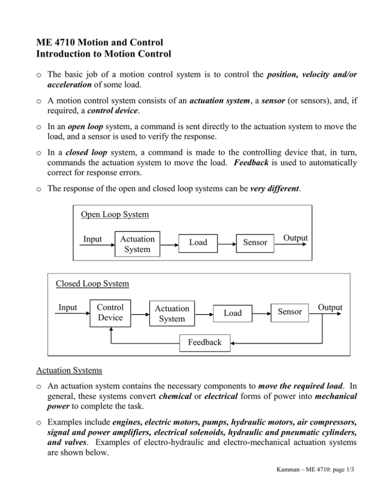
ME 4710 Motion and Control Introduction to Motion Control o The basic job of a motion control system is to control the position, velocity and/or acceleration of some load. o A motion control system consists of an actuation system, a sensor (or sensors), and, if required, a control device. o In an open loop system, a command is sent directly to the actuation system to move the load, and a sensor is used to verify the response. o In a closed loop system, a command is made to the controlling device that, in turn, commands the actuation system to move the load. Feedback is used to automatically correct for response errors. o The response of the open and closed loop systems can be very different. Open Loop System Input Actuation System Load Sensor Output Closed Loop System Input Control Device Actuation System Load Sensor Output Feedback Actuation Systems o An actuation system contains the necessary components to move the required load. In general, these systems convert chemical or electrical forms of power into mechanical power to complete the task. o Examples include engines, electric motors, pumps, hydraulic motors, air compressors, signal and power amplifiers, electrical solenoids, hydraulic and pneumatic cylinders, and valves. Examples of electro-hydraulic and electro-mechanical actuation systems are shown below. Kamman – ME 4710: page 1/3 Electric Motor Hydraulic Pump Valve Hydraulic Cylinder Output Input Input Power Amplifier DC Motor Lead Screw Drive Output Sensors o Sensors are used to monitor the behavior of the system. They should provide accurate and timely measurements of important variables within the system. o Examples include strain gages, pressure gages/transducers, force gages/transducers, flow meters, limit switches, potentiometers, linear variable differential transformers (LVDT), accelerometers, tachometers, encoder wheels, thermocouples, and resistance temperature detectors (RTD). o Sensors may be used to measure the position, velocity and acceleration of the load; however, additional sensors may be used to measure other important variables in the system. o In an electro-hydraulic actuation system, there may also be feedback of the valve spool position and fluid pressure and flow rate. o In an electro-mechanical system, there may also be feedback of the motor speed. o The use of additional sensors and feedback loops makes the system more complicated and costly, but it may increase system performance if well designed. Control Device o The control device may have analog circuits, digital circuits, or both. In either case, the control device must have the ability to form differences (or sums), amplify, integrate, and differentiate in order to behave as our control loop design requires. o Analog circuits depend heavily on the use of operational amplifiers (called Op-Amps). Digital control devices are implemented using microprocessors either in a PC-based system, a microcontroller, or a program logic controller (PLC). Kamman – ME 4710: page 2/3 o PLC’s are very commonly used in industrial control applications requiring continual operation. PC-based control devices are more commonly used in testing, development, and research environments. o Analog-to-digital (A/D) and digital-to-analog (D/A) converters are required for digital control devices to interface with analog processes. Two important characteristics of these converters is their speed and resolution. o Speed is affected by the raw speed of the converter and the number of channels a converter supports. In some systems, each channel of data has its own dedicated converter, while in others a single converter is shared by multiple channels by using a multiplexer. o Resolution is determined by the number of bits used in the conversion process. The quantization error for a converter using n bits in the conversion process is eQ Vmax Vmin . 2n 1 Here, Vmax Vmin represents the maximum voltage range of the converter. It is important to use the full range of the converters and use enough bits to provide the desired resolution. Kamman – ME 4710: page 3/3

