Cisco 11500 Series Content Services Switch
Switch Control Module Reference
The CSS 11500 series Switch Control Module (SCM) provides master control and is responsible for the
following functions: system powerup and boot control, centralized routing table management,
system-wide connection management, and interface to an external Network Management Station.
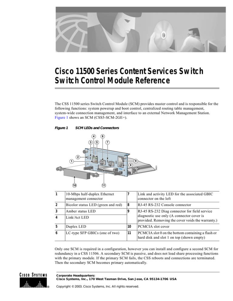
Figure 1 shows an SCM (CSS5-SCM-2GE=).
Figure 1
SCM LEDs and Connectors
4
6
3
5
7
MANAGEM
ENT
10BASE-T
GE 1
CSS5-SCM-2GE
1
DUPLEX
LINK
GE 2
PCMCIA
9
LINK
8
SLOT 1
SLOT 0
10
CONSOLE
59531
2
LINK/ACT
System Control
STATUS
11
1
10-Mbps half-duplex Ethernet
management connector
7
Link and activity LED for the associated GBIC
connector on the left
2
Bicolor status LED (green and red)
8
RJ-45 RS-232 Console connector
3
Amber status LED
9
4
Link/Act LED
RJ-45 RS-232 Diag connector for field service
diagnostic use only (A connector cover is
provided. Removing the cover voids the warranty.)
5
Duplex LED
10
PCMCIA slot cover
6
LC-type SFP GBICs (one of two)
11
PCMCIA slot 0 on the bottom containing a flash or
hard disk and slot 1 on top (shown empty)
Only one SCM is required in a configuration, however you can install and configure a second SCM for
redundancy in a CSS 11506. A secondary SCM is passive, and does not load share processing functions
with the primary module. If the primary SCM fails, the CSS reboots and connections are terminated.
Then the secondary SCM becomes primary automatically.
Corporate Headquarters:
Cisco Systems, Inc., 170 West Tasman Drive, San Jose, CA 95134-1706 USA
Copyright © 2003. Cisco Systems, Inc. All rights reserved.
Note
Before you remove or install a module, make sure you properly ground yourself prior to handling the
module. For example, wear an antistatic wrist strap (included in the kit with the module) and stick
the copper-tape end of the strap to an unpainted metal surface on the chassis. Make sure that the wrist
strap makes good contact with your skin.
Removing the SCM
Caution
You must power down the CSS to remove an SCM. If you remove a powered-on SCM from an
operational CSS, the CSS terminates all communications and reboots.
To remove an SCM:
1.
Locate the failed SCM (its Status LEDs will be off). See Figure 1.
2.
If necessary, power down the CSS.
3.
Remove all cables from the module.
4.
With a Phillips screwdriver, remove the PCMCIA cover and then loosen the spring-loaded screws
on the front of the module faceplate. See Figure 2.
Figure 2
Removing the PCMCIA Cover from the SCM
MANAGEM
ENT
10BASE-T
DUPLEX
CSS5-SCM-2GE
GE 1
GE 2
PCMCIA
LINK
SLOT 1
SLOT 0
5.
LINK
CONSOLE
59602
LINK/ACT
System Control
STATUS
Extend both ejectors simultaneously to unseat the module connector from the backplane and slide
the module out of the slot.
Cisco 11500 Series Content Services Switch Switch Control Module Reference
2
78-13711-03
Remove the SFP GBICs from the SCM. Press the ejectors on the SFP GBICs. Slide them out of the
module and set them aside. See Figure 3.
6.
Figure 3
Ejecting the SFP GBIC from the SCM
MANAGEMEN
10BASE-T T
LINK/ACT
DUPLEX
GE 1
LINK
SLOT 1
3
SLOT 0
CONSOLE
67902
2
CSS5-SCM-2GE
1
LINK
GE 2
PCMCIA
System Control
STATUS
1
1
SFP GBIC ejector
7.
Remove the flash or hard disks from the SCM. Press the ejectors to the right of the disks. Slide them
out of the module and set them aside. See Figure 4.
Figure 4
Ejecting the Disk from the SCM
MANAGEMEN
10BASE-T T
LINK/ACT
DUPLEX
2
3
LINK
GE 2
LINK
SLOT 1
SLOT 0
CONSOLE
59532
1
CSS5-SCM-2GE
GE 1
PCMCIA
System Cont l
STATUS
1
1
Note
Disk ejector
The replacement SCM contains a 144 MB Small Outline RamBus Inline Memory Module
(SO-RIMM). If your failed module has a 288 MB SO-RIMM, you must remove its SO-RIMM, and
place it in the replacement SCM. See “Removing and Replacing the Memory Module” later in this
document.
Installing the SCM
To install an SCM (refer to the previous illustrations):
1.
Properly ground yourself prior to handling the module, as noted on the previous page .
2.
If applicable, reinstall the memory module, SFP GBICs, and flash or hard disks in the SCM.
3.
Locate the slot in the chassis for the SCM. SCMs are restricted to slots 1 and 2.
Cisco 11500 Series Content Services Switch Switch Control Module Reference
78-13711-03
3
4.
Insert the module into the board guides at the left and right sides of the slot, and then slide the
module into the chassis by pressing firmly at the left and right of the faceplate.
5.
Close both ejectors simultaneously to seat the module connector into the backplane.
6.
Using a Phillips screwdriver, tighten the spring-loaded screws on the front of the module faceplate.
7.
With a Phillips screwdriver, replace the PCMCIA cover (see Figure 2) and then tighten the
spring-loaded screws on the front of the module faceplate.
8.
Replace the cables. Note that the SFP GBICs have LC-type connectors and require LC-type fiber
cables.
9.
Reboot the CSS.
10. If you installed a secondary SCM, use the passive sync command to copy the boot config from the
primary SCM to the secondary SCM.
If you installed a replacement for a primary SCM, the replacement has default settings for the
administrative username and password, IP address, subnet mask, and primary boot record. To
reconfigure these parameters, access the Offline Diagnostic Monitor menu at the boot prompt. For
information on using the Offline Diagnostic Monitor menu, refer to the Content Services Switch
Administration Guide.
Table 1 describes the SCM LEDs and their indications.
Table 1
Switch Control Module LED Descriptions
LED Name
Color
State
Indicates
Status (left)
Green
Solid
The module is ready.
Variable blink
Disk activity is occurring.
Slow blink
Another CSS module has failed.
Solid
The module failed the power-up self test during the boot
process.
Slow blink
The module failed.
Red
Status (right)
No color Off
The module failed and has no power.
Amber
Slow blink
The module is offline and active.
Solid
The module is online and not active (secondary).
Off
There is no link.
On
The link is established but there is no activity.
Blinking
The link is established with transmit or receive activity.
Off
There is no link.
On
The link exists and synchronization is achieved.
Blinking
The link is established with transmit and receive activity.
Link/Act
Green
for the Ethernet
Management Port
Link
for each Gigabit
Ethernet Port
Green
Related CLI Commands
To view the current state of the SCM and verify it is powered on as indicated by the primary or secondary
state, use the show chassis command.
Cisco 11500 Series Content Services Switch Switch Control Module Reference
4
78-13711-03
Removing and Replacing the Memory Module
To remove and replace a memory module:
1.
Place the module face up on a flat antistatic surface.
2.
Locate the SO-RIMM connector on the rear of the module. See Figure 5.
Figure 5
Memory Module Location
System Control
59620
1
1
Memory module
3.
Slightly extend the locking tabs on both sides of the memory module to release it. Gently pull the
module out of the connector. See Figure 6.
Figure 6
Memory Replacement
59547
1
1
SO-RIMM connector tab
4.
Align the replacement memory module so that the row of gold contacts on the memory module are
facing the row of gold pins inside the connector.
5.
Insert the memory module into the connector at approximately a 30 degree angle (see Figure 6) and,
with gentle pressure, push the module into the connector until the module fits snugly against the
back of the connector. At this point, the module is still at an angle above the locking tabs.
6.
Gently push straight down on the edges of the module until the tabs lock it into place.
Cisco 11500 Series Content Services Switch Switch Control Module Reference
78-13711-03
5
Cisco 11500 Series Content Services Switch Switch Control Module Reference
6
78-13711-03


