A PASSIVE MICRO DIRECT METHANOL FUEL CELL WITH CROSS-STRUCTURE CATHODE
advertisement

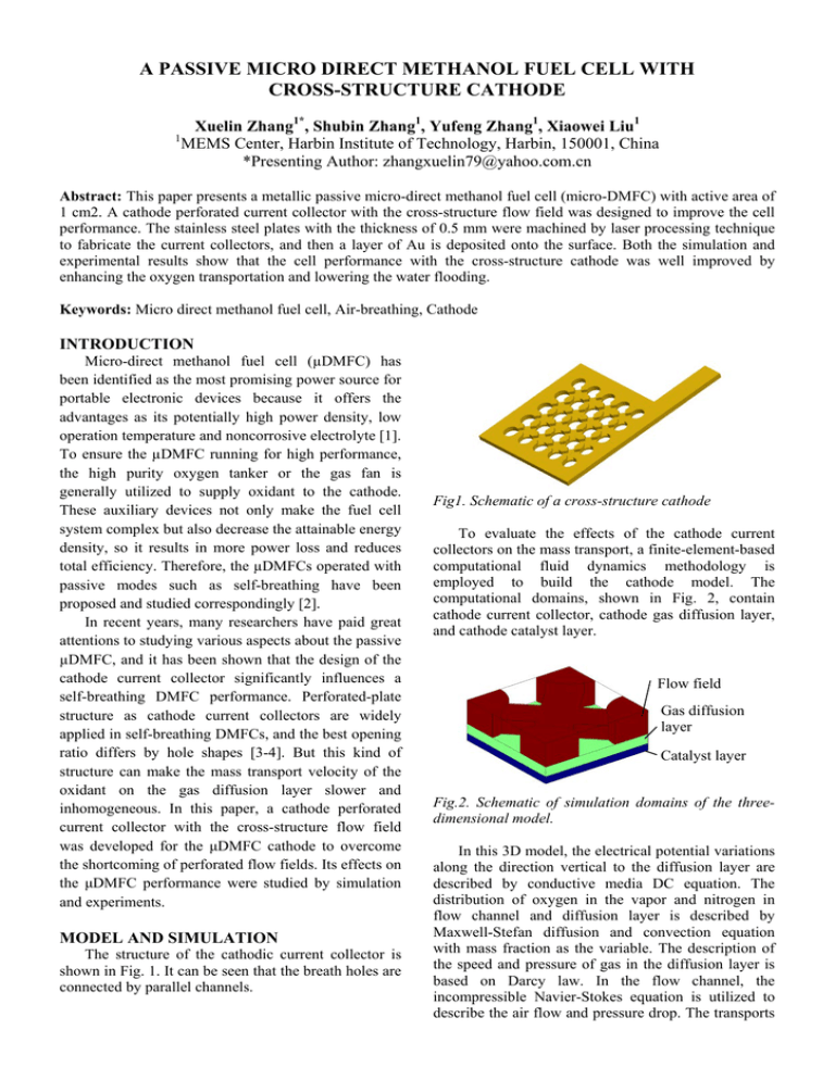
A PASSIVE MICRO DIRECT METHANOL FUEL CELL WITH CROSS-STRUCTURE CATHODE 1 Xuelin Zhang1*, Shubin Zhang1, Yufeng Zhang1, Xiaowei Liu1 MEMS Center, Harbin Institute of Technology, Harbin, 150001, China *Presenting Author: zhangxuelin79@yahoo.com.cn Abstract: This paper presents a metallic passive micro-direct methanol fuel cell (micro-DMFC) with active area of 1 cm2. A cathode perforated current collector with the cross-structure flow field was designed to improve the cell performance. The stainless steel plates with the thickness of 0.5 mm were machined by laser processing technique to fabricate the current collectors, and then a layer of Au is deposited onto the surface. Both the simulation and experimental results show that the cell performance with the cross-structure cathode was well improved by enhancing the oxygen transportation and lowering the water flooding. Keywords: Micro direct methanol fuel cell, Air-breathing, Cathode INTRODUCTION Micro-direct methanol fuel cell (µDMFC) has been identified as the most promising power source for portable electronic devices because it offers the advantages as its potentially high power density, low operation temperature and noncorrosive electrolyte [1]. To ensure the µDMFC running for high performance, the high purity oxygen tanker or the gas fan is generally utilized to supply oxidant to the cathode. These auxiliary devices not only make the fuel cell system complex but also decrease the attainable energy density, so it results in more power loss and reduces total efficiency. Therefore, the µDMFCs operated with passive modes such as self-breathing have been proposed and studied correspondingly [2]. In recent years, many researchers have paid great attentions to studying various aspects about the passive µDMFC, and it has been shown that the design of the cathode current collector significantly influences a self-breathing DMFC performance. Perforated-plate structure as cathode current collectors are widely applied in self-breathing DMFCs, and the best opening ratio differs by hole shapes [3-4]. But this kind of structure can make the mass transport velocity of the oxidant on the gas diffusion layer slower and inhomogeneous. In this paper, a cathode perforated current collector with the cross-structure flow field was developed for the μDMFC cathode to overcome the shortcoming of perforated flow fields. Its effects on the μDMFC performance were studied by simulation and experiments. MODEL AND SIMULATION The structure of the cathodic current collector is shown in Fig. 1. It can be seen that the breath holes are connected by parallel channels. Fig1. Schematic of a cross-structure cathode To evaluate the effects of the cathode current collectors on the mass transport, a finite-element-based computational fluid dynamics methodology is employed to build the cathode model. The computational domains, shown in Fig. 2, contain cathode current collector, cathode gas diffusion layer, and cathode catalyst layer. Flow field Gas diffusion layer Catalyst layer Fig.2. Schematic of simulation domains of the threedimensional model. In this 3D model, the electrical potential variations along the direction vertical to the diffusion layer are described by conductive media DC equation. The distribution of oxygen in the vapor and nitrogen in flow channel and diffusion layer is described by Maxwell-Stefan diffusion and convection equation with mass fraction as the variable. The description of the speed and pressure of gas in the diffusion layer is based on Darcy law. In the flow channel, the incompressible Navier-Stokes equation is utilized to describe the air flow and pressure drop. The transports of electron and proton are respectively controlled by solid phase electronic potential and membrane ionic potential. As the overlay region of solid and electrolyte, the catalyst layer provides the reaction channel for electron, proton and related reaction molecular, which enhances the successful reaction. Obviously, the electronic current flows in the diffusion layer and the catalyst layer, while the ionic current resides in the catalyst layer and the PEM. The detailed simulation process is similar to that adopted in ref. [5]. COMSOL Multiphysics 3.6 was used to perform the computation to obtain the simulation results. breathing area and decreases the area under the current collector, which results in more fluent oxygen supply and increases the power density of the cell. (a) (a) (b) Fig. 4. Liquid saturation distribution of the catalyst layer with the perforated cathode (a) and crossstructure cathode (b). (b) Fig. 3. Oxygen concentration distribution of the catalyst layer with the perforated cathode (a) and cross-structure cathode (b). Fig. 4 shows the liquid saturation distribution of the catalyst layer. The improved cathode structure also makes the catalyst layer possess a lower and more even liquid saturation than the conventional one, which is beneficial for the water discharge and thus increases the performance stability of the microDMFC. FABRICATION AND ASSEMBLY Oxygen concentration distribution of the catalyst layer with the perforated cathode and cross-structure are shown in Fig. 3. The oxygen distribution on the cathode catalyst layer is more even in the improved structure than that in the conventional one. The minimum oxygen concentration in the improved structure is about 9.3mol/m3, higher than that in the planar cathode structure (9.25mol/m3). The flow channel in the improved cathode structure enlarges the The stainless steel plates with the thickness of 0.5 mm were machined by laser processing technique to fabricate the current collectors. A layer of Au is deposited onto the surface of current collectors for good electrical conductivity and excellent anticorrosion resistance. The MEA is consisted of Nafion® 117 produced by DuPont©. Catalyst loading on the anode side is 4.0mg/cm2 of Pt-Ru/C (proportion 1:1), while the catalyst loading on the cathode side is 4.0mg/cm2 of Pt/C. The carbon papers (produced by Toray Industries, Japan) are used as the diffusion layer on the both anode and cathode sides. Ultimately, the MEA was sandwiched between anode current collector and cathode current collector, and then the screws were used to create an integrated. The process of assemble micro-DMFC is shown in Fig. 5. structure cathode, the open-circuit voltage and maximum power density were increases from 650mV to 690mV, and from 18mW/cm2 to 26mW/cm2, respectively. This indicates the feasibility and advantages of the cross-structure cathode. According to the simulation, this increase should be ascribed to the improvement of oxygen transportation. Fig.5: Schematic of micro-DMFC RESULTS AND DISCUSSIONS I–V polarization curves were recorded using a test station (Arbin FCT system, Arbin Inc.) with a 3 M methanol solution. For each discharging current point along a polarization curve, a 2 minute waiting time was used to obtain a stable voltage. Prior to the test, MEAs were pretreated by assembled them into a cell with the cathode closed and the anode reservoir filled with a 2–3 M methanol solution, for a period of about 12 h. As a preconditioning step, at least 3 I–V polarization runs were conducted using 3 M methanol solution fed to the anode at 60℃. Fig. 7. Duration tests of the micro-DMFCs with different cathode structures. During the long-term operation of the passive DMFCs, a portion of the water generated in the cathode turns into the liquid state and stays on the surface of the catalyst layer. This prevents oxygen from joining the reaction. Meanwhile, the active area of the electrode declines, which gradually degrades the cell performance and leads to marked variations. Fig. 7 shows the test result of the transient performance at 80mAcm−2 with duration of 600 min. As shown, there were obvious variations in the output of the perforated cathode, followed by a gradual decrease after about 300 min. The cross-structure cathode showed a relatively stable performance and improved capability for discharging water. CONCLUSIONS In this paper, a new cross-structure cathode was designed and fabricated to improve the performance of a passive micro direct methanol fuel cell. To evaluate the effects of the cathode current collectors on the mass transport, a finite-element-based computational fluid dynamics methodology is employed to build the cathode model. Compared with the conventional perorated cathode structure, the new one can improve the cell performance and long-term operation stability. Fig. 6. Performances of the micro-DMFCs with different cathode structures. Fig. 6 shows the test results on the performance. The findings show that compared with the perforated cathode, while the contact area between the diffusion layer and the board was decreased in the cross- ACKNOWLEDGEMENT This work is supported by the National Natural Science Funds of China (No. 60806037 and 61076105) and the Fundamental Research Funds for the Central Universities (Grant No. HIT. NSRIF. 2010075). REFERENCES [1] [2] [3] [4] [5] [6] S.K. Kamarudin, F. Achmad, W.R.W. Daud. Overview on the application of direct methanol fuel cell (DMFC) for portable electronic devices, International Journal of Hydrogen Energy, 34 (2009): 6902. T.S. Zhao, R. Chen, W.W. Yang, C. Xu. Small direct methanol fuel cells with passive supply of reactants. Journal of Power Sources, 191 (2009): 185. Hwang JJ, Wu SD, Lai LK, Chen CK, Lai DY. Effect of breathing hole size on the electrochemical species in a free-breathing cathode of a DMFC. Journal of Power Sources, 161 (2006): 240. Jung Guo-Bin, Su Ay, Tu Cheng-Hsin, Lin YurTsai, Weng Fang-Bor, Chan Shih-Hung. Effects of cathode flow fields on direct methanol fuel cell-simulation study. Journal of Power Sources, 171 (20071): 212. Hwang JJ, Chao CH. Species-electrochemical transports in a free-breathing cathode of a PCBbased fuel cell. Electrochimica Acta, 52(2007): 1942. X. W. Liu, Y. F. Zhang, H. He, Z. Y. Yuan. A self-breathing micro direct methanol fuel cell with a spoke cathode structure. Applied Physics Letters, 97 (2010): 204102.


