Advances in Film / Screen Radiography AgX Photodetector AgX Photodetectors
advertisement
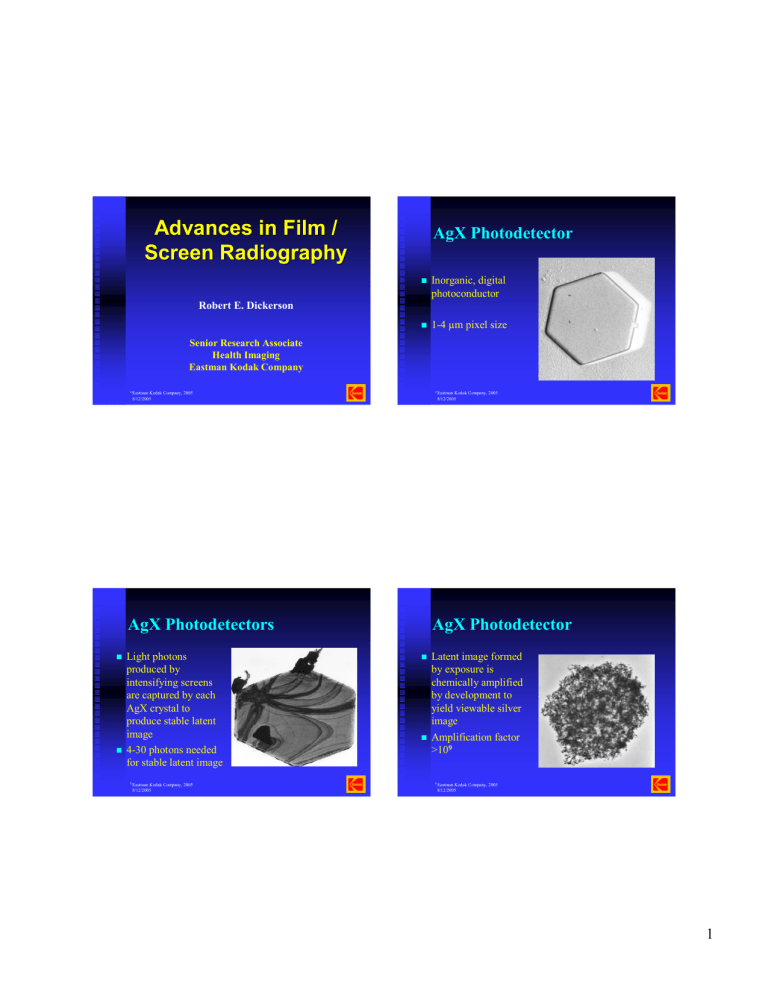
Advances in Film / Screen Radiography AgX Photodetector Inorganic, digital photoconductor Robert E. Dickerson 1-4 µm pixel size Senior Research Associate Health Imaging Eastman Kodak Company ©Eastman Kodak Company, 2005 8/12/2005 ©Eastman Kodak Company, 2005 8/12/2005 AgX Photodetectors AgX Photodetector Light photons produced by intensifying screens are captured by each AgX crystal to produce stable latent image 4-30 photons needed for stable latent image Latent image formed by exposure is chemically amplified by development to yield viewable silver image Amplification factor >109 ©Eastman Kodak Company, 2005 8/12/2005 ©Eastman Kodak Company, 2005 8/12/2005 1 Tabular vs Conventional, 3-D crystals ©Eastman Kodak Company, 2005 8/12/2005 Cubic Grain Microcrystals ©Eastman Kodak Company, 2005 8/12/2005 Non Commercialized Micro crystals ©Eastman Kodak Company, 2005 8/12/2005 X-Wing Fighter ©Eastman Kodak Company, 2005 8/12/2005 2 PACMAN Opportunities for Improved Film Design Higher contrast by control of grain size distribution and sensitivity Higher resolution film/screen systems Improved quantum sensitivities of silver halide microcrystals Novel coating structures to improve film processing rates New display properties ©Eastman ©Eastman Kodak Company, 2005 8/12/2005 Kodak Company, 2005 8/12/2005 KODAK MIN-R EV Film New asymmetric coating structure, in conjunction with novel emulsions, optimizes image quality from toe to shoulder of the response and improves physical properties. ion een muls E ary ) e u l n t (B lsio or u pp Em er Su ry ay d a n L er n co tio ay Se ala n L tih tio An nta ie Or Scr im Pr Total ©Eastman Kodak Company, 2005 8/12/2005 Parenchymal Emulsion Novel silver halide microcrystals in the parenchymal emulsion contain shallow electron trapping dopants. In conjunction with the improved monodispersity of the grains, this allows it to achieve high contrast with a sharp toe. High contrast makes breast anatomy, including abnormalities, more visible Sharp toe might enable new optimization of imaging chain and better visualization of microcalcifications ©Eastman Kodak Company, 2005 8/12/2005 3 Min-R EV 150 system vs. system vs KODAK MIN-R EVMin-R 1502000 Screen KODAK MIN-R 2000 Screen 6.5 High D-max and shoulder contrast is due to high opacity grains and backside emulsion 6.0 5.5 Density Higher 5.0 contrast 4.5 to is due 4.0 monodisperse 3.5 cubic grains Results in greater overexposure latitude, which is due to higher upper scale contrast 3.0 2.5 Better2.0visualization of breast 1.5 1.0 parenchyma Sharp toe is due to novel emulsion technology 0.5 Images were exposed to a density of ~1.9 in the center of the image Images made with a GE DMR mammographic unit Two imaging systems: MIN-R 2000 and MIN-R EV Eight kVps: 25-32 Two anode/filter combinations: Mo/Mo and Rh/Rh Two duplicate sets 0.0 0.0 0.5 1.0 1.5 2.0 Log E X-ray Sensitometry KODAK MIN-R 2000/2000 Screens KODAK MIN-R EV & EV 150 Screens ©Eastman Kodak Company, 2005 Kodak Company, 2005 8/12/2005 8/12/2005 ©Eastman CDMAM Phantom, Type 3.4, used in the study Gold disks range in diameter from 60 µm to 2 mm, and in thickness from 30 nm to 2 µm Each square contains two identical disks, one in the center and one in a randomly chosen corner The task is to pick the corner containing the disk ©Eastman ©Eastman Kodak Kodak Company, Company,2004 2005 8/12/2005 8/12/2005 2.5 Results in whiter whites, more “sparkle,” improved visibility of microcalcifications Total of 64 images All processed in KODAK X-OMAT EX II Developer and Replenisher ©Eastman Kodak Company, 2005 8/12/2005 Score sheet from one observer for MIN-R 2000 Film/Screen, 26 kVp, Mo/Mo Blue indicates that the correct corner was identified Red indicates that the wrong corner was identified or that the observer said they could no longer detect the disks ©Eastman ©Eastman Kodak Kodak Company, Company,2004 2005 8/12/2005 8/12/2005 4 Summary Phantom: CDMAM Phantom, Type 3.4 Results System kVp Filtration CDMAM Detectability* Exposure Time (sec) Relative Mid-line Dose MIN-R 2000 MIN-R 2000 28 30 Mo/Mo Rh/Rh 0 −2 1.92 0.60 1.0 0.4 MIN-R EV MIN-R EV 28 30 Mo/Mo Rh/Rh +2 0 1.68 0.55 0.9 0.4 * Average relative column number ©Eastman ©Eastman Kodak Company, 2005 8/12/2005 At 28 kVp, Mo/Mo, the MIN-R EV System will reduce the mid-line dose by 10%, yet provide better detection of the disks in the CDMAM Phantom than the MIN-R 2000 System At 30 kVp, Rh/Rh, the MIN-R EV System will provide similar detection of the disks in the CDMAM Phantom as a MIN-R 2000 System but at 40% the mid-line dose Kodak Company, 2005 8/12/2005 KODAK Hyper Speed G Medical Film (Provides improved resolution and visually adaptive contrast) MIN-R EV Systems demonstrate simultaneously high sharpness and low, high-frequency noise ©Eastman Kodak Company, 2005 8/12/2005 Features oxidatively enhanced, high quantum efficiency AgX microcrystal that provides improved sensitivity Because of the improved film properties (toe contrast, midscale contrast, speed) and improved screen properties (improved MTF, speed) KODAK Hyper Speed G Medical Film Low Exposure Region Imaging Layer Hyper Speed G 0.30 logE faster High Exposure Imaging Layer + Gradient Crossover Control T-MAT G/RA Support ©Eastman Kodak Company, 2005 8/12/2005 5 Radiographic Speed – Historical Timeline 1896: Paper used for media-based radiography. Calcium tungstate intensifying screens discovered. Relative speeds unknown (VERY low). Modulation Transfer Function (image blur) Screen / Film Speed MTF (cycles/mm) 2 4 8 400 100% 100% 100% 800 175% 250% 270% 1912: Glass plate radiography. VERY low speed. 1918-1970s: Double-emulsion films, calcium tungstate screens improved, relative system speeds 25-200. 1970s – present: Rare earth screens and appropriate films commercialized, relative system speeds 100-400 (A few small niche markets use faster systems). 2004: Hyper-speed systems, relative system speeds 400-1600 (with greatly improved high-frequency NEQ and DQE). ©Eastman Screen / Film Speed MTF (cycles/mm) 2 4 8 LANEX Regular / T-MAT G 400 100% 100% 100% ©Eastman Kodak Company, 2005 8/12/2005 1300 90% 95% 100% Kodak Company, 2005 8/12/2005 Modulation Transfer Function (image blur) GE Digital Radiography Computed Radiography X-SIGHT / Hyper Speed G LANEX Fast / Hyper Speed G ©Eastman Kodak Company, 2005 8/12/2005 INSIGHT Skeletal Medium / Hyper Speed G LANEX Fine / Hyper Speed G LANEX Regular / T-MAT G How Hyper Speed Works, cont. MTF benefit can be utilized in two basic ways: 1. Provide improved image quality (better visibility of fine detail) at current system speeds. 400 250% 500% 750% OR 200 300% 600% 900% 2. Provide clinically acceptable, high image quality at 2X current system speeds, exchanging potential 200-400 150% 60% NA 200-400 90% 60% NA image quality for radiation dose reduction. ©Eastman Kodak Company, 2005 8/12/2005 6 Benefits of High-Speed Systems What does this mean? Mammographic – MTF at 200200-300 speed X-SIGHT – MTF at 800 speed LANEX Regular/TRegular/T-MAT – MTF at 1300 speed ©Eastman Higher image quality from stopping motion grids, body motion Opportunity to reduce Kv Smaller focal spot Magnification Increased tube life Reduced radiation dose to radiology staff ©Eastman Kodak Company, 2005 8/12/2005 Kodak Company, 2005 8/12/2005 Visually Adaptive Contrast The human visual system loses it’s ability to distinguish differences in density as an image gets darker. Visually Adaptive Contrast Visually adaptive contrast puts the contrast where the eyes need it. Visually Adaptive Contrast This means that lesion detection is less likely if the lesion appears in a darker area of the radiograph. More Lesion Detectability Film Contrast Lesion Detectability Lesion Detection vs Density More Lower Less Less Light Light ©Eastman Higher Kodak Company, 2005 8/12/2005 Film Density Film Density Dark Dark ©Eastman Kodak Company, 2005 8/12/2005 7 KODAK X-SIGHT L/RA Film Visually Adaptive Contrast Local contrast comparison with other of Kodak’s latitude systems X-RAY SENSITOMETRY SPEED MATCHED AT D = 1.20 4.0 T-MAT L/RA & LANEX Regular X-SIGHT L/RA & X-SIGHT XLA+ & TRIMATIC Regular 3.5 3.0 Gamma 2.5 2.0 1.5 1.0 0.5 0.0 0.0 0.5 1.0 1.5 2.0 Summary New film/screen system allows for significantly reduced X-ray dose at improved MTF (image blur). Significant improvements in system MTF are possible at equivalent X-ray doses New film/screen system provide opportunities for dose reduction as result of higher system speed while maintaining high image quality 2.5 log10 Relative Exposure ©Eastman Kodak Company, 2005 8/12/2005 ©Eastman Kodak Company, 2005 8/12/2005 Conclusion Improved film/screen systems continue to be developed. Opportunities for improved image quality and processability still exist. New systems provide possibilities for lower-dose radiology at high image quality. ©Eastman Kodak Company, 2005 8/12/2005 ©Eastman Kodak Company, 2005 8/12/2005 8
