Spectral Line Emission/Absorption Individual atoms produce/absorb light only at precise discrete energies
advertisement
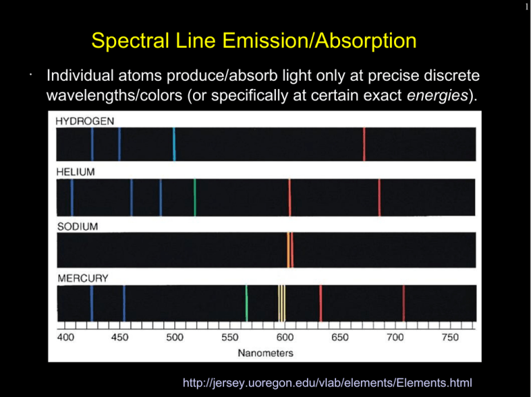
1 Spectral Line Emission/Absorption • Individual atoms produce/absorb light only at precise discrete wavelengths/colors (or specifically at certain exact energies). http://jersey.uoregon.edu/vlab/elements/Elements.html 2 Spectral Line Emission/Absorption • This property arises from the discrete nature of electronic “orbits” in atoms. • Electrons can only be in configurations that have a specific energy. Jumping between these configurations (higher to lower energy) emits light. A photon of exactly the right energy can kick an electron from a lower to higher energy. http://jersey.uoregon.edu/vlab/elements/Elements.html 3 Spectral Line Emission/Absorption • This property arises from the discrete nature of electronic “orbits” in atoms. • Electrons can only be in configurations that have a specific energy. Jumping between these configurations (higher to lower energy) emits light. Conversely, a photon of exactly the right energy can kick an electron from a lower to higher energy. http://jersey.uoregon.edu/vlab/elements/Elements.html 4 A Classical Approach to Atomic Energy Levels Consider the electron in orbit around the atomic nucleus (in this case a proton) held in orbit by the electrostatic attraction between two opposite charges. 2 1 Ze F elec = 4πϵ 0 r 2 me v F centrip = r Z is the atomic number of the nucleus, 1 for hydrogen e is the electronic charge 1.6x10⁻¹⁹ coulomb εo is the permittivity of free space, 8.9x10⁻¹² Farad s-1 me is the mass of the electron 2 5 A Classical Approach to Atomic Energy Levels Consider the electron in orbit around the atomic nucleus held in orbit by the electrostatic attraction between two opposite charges. 2 1 Ze F elec = 4πϵ 0 r 2 me v F centrip = r 2 Add a quantum mechanical twist – that the angular momentum is quantized in integer multiples (n) of h/2π. nh me v r = 2π 6 A Classical Approach to Atomic Energy Levels Equating the force laws and substituting in the quantized angular momentum equation to get rid of “v” we get: ϵ0 h 2 −11 5 . 29x10 meters 2 r ( n)= n = n 2 Z πZe m e me v 2 F centrip = r m e vr= 2 1 e2 F elec = 4πϵ 0 r 2 nh 2π 7 A Classical Approach to Atomic Energy Levels What is the energy of an orbit as a function of r(n)? Equate the force equations and rearrange to get ½ mv 2 for K.E. 2 Ze K . E .= 8πϵ 0 r 2 Ze P . E .=− 4πϵ 0 r 2 Ze Total=− 8πϵ 0 r ( n ) me v F centrip = r m e vr= 2 nh 2π 2 1 e F elec = 4πϵ 0 r 2 ϵ0 h 2 5 . 29x10−11 meters 2 r ( n)= n = n 2 Z πZe m e 2 8 A Classical Approach to Atomic Energy Levels The energy of each quantized level depends inversely on the level number squared. The difference in energy between levels (and thus the energy of a radiated or absorbed photon is: 13.6 eV E (n) = 2 n eV = electron volt, the energy an electron has if it is accelerated across a potential of one volt 1 ev = 1.6 x 10⁻¹⁹ Joules ϵ0 h 2 5 . 29x10−11 meters 2 r ( n)= n = n 2 Z πZe m e 1 e2 F elec = 4πϵ 0 r 2 2 me v F centrip = r 2 m e vr= nh 2π 9 A Classical Approach to Atomic Energy Levels The energy of each quantized level depends inversely on the level number squared. The difference in energy between levels (and thus the energy of a radiated or absorbed photon is: ΔE= 13 .6eV eV = electron volt, the energy an electron has if it is accelerated across a potential of one volt 1 ev = 1.6 x 10⁻¹⁹ Joules [ 1 2 nlower − ϵ0 h 1 2 n upper ] 2 5 . 29x10−11 meters 2 r ( n)= n = n 2 Z πZe m e 1 e2 F elec = 4πϵ 0 r 2 2 me v F centrip = r 2 m e vr= nh 2π 10 A Classical Approach to Atomic Energy Levels The energy of each quantized level depends inversely on the level number squared. The difference in energy between levels (and thus the energy of a radiated or absorbed photon is: [ 91. 2 1 1 λ= 2 nm 2 − 2 Z nlower n upper me v F centrip = r m e vr= 2 nh 2π −1 ] 2 1 e F elec = 4πϵ 0 r 2 ϵ0 h 2 5 . 29x10−11 meters 2 r ( n)= n = n 2 Z πZe m e 2 11 A Classical Approach to Atomic Energy Levels A “series” of hydrogen lines has a common lower state ∆n = 1 is “alpha”, ∆n = 2 is “beta”.... 1 = Lyman (ultraviolet), Lyman 2 = Balmer (visible), Balmer 3 = Paschen (near infrared) 4 = Brackett (infrared), Brackett 5 = Pfund (infrared) 6 = Humphries (infrared) [ α is 121.6 nm α, known as Hα, is 656.3 nm γ is 2165 nm 91. 2 1 1 λ= 2 nm 2 − 2 Z nlower n upper −1 ] 12 13 Radiative Lifetime Accelerated charges radiate. Consider an electron in the 2nd hydrogen energy level. How long does it take, classically, to radiate enough energy to reach the energy of the 1st level? Answer = 3x10⁻⁹ s where you get half that for a formal quantum mechanical solution. Bottom line – an excited state decays quite rapidly emitting a photon equal in energy (wavelength) to the energy difference between levels. “Selection rules” driven by quantum mechanical principles (exclusion law, angular momentum restrictions) limit allowed transitions and can make lifetimes substantially longer that this simple classical result. 14 Spectral Line Emission/Absorption • This property arises from the discrete nature of electronic “orbits” in atoms. • Electrons can only be in configurations that have a specific energy. Jumping between these configurations (higher to lower energy) emits light. A photon of exactly the right energy can kick an electron from a lower to higher energy. 15 Spectral Line Emission/Absorption • This property arises from the discrete nature of electronic “orbits” in atoms. • Electrons can only be in configurations that have a specific energy. Jumping between these configurations (higher to lower energy) emits light. A photon of exactly the right energy can kick an electron from a lower to higher energy. http://jersey.uoregon.edu/vlab/elements/Elements.html 16 Spectral Line Emission/Absorption • Spectral lines can reveal the elemental content of a planet or star's atmosphere. • Line intensity reveals both the quantity of the element as well as the temperature. http://jersey.uoregon.edu/vlab/elements/Elements.html 17 Spectral Line Emission/Absorption • Spectral line absorption arises when light from a continuous source passes through a cold gas. The gas atoms selectively remove (actually scatter) specific colors/energies. 18 The Doppler Shift • The observed wavelength of a spectral line depends on the velocity of the source toward or away from the observer. • The amount of the shift is proportional to the object's velocity relative to the speed of light (so typically the shift is tiny but measurable). λ shifted − λ rest λ rest Δλ v = = λrest c 19 The Doppler Shift • Objects approaching an observer have wavelengths artificially shifted toward shorter wavelengths – a blueshift. Objects moving away toward longer wavelengths – a redshift Note that these are directions in the electromagnetic spectrum, not absolute colors. λ shifted − λ rest λ rest Δλ v = = λrest c The Doppler Shift • λ shifted − λ rest λ rest 20 Δλ v = = λrest c Using the Doppler Shift we can measure the subtle motions (towards or away from us) of stars, galaxies and interstellar gas without ever seeing actual movement! 21 Spectral Line Emission/Absorption • Doppler velocities of individual atoms in a gas broaden spectral lines in a way that is characteristic of the temperature and density. http://jersey.uoregon.edu/vlab/elements/Elements.html 22 Spectral Line Emission/Absorption • Collisions between atoms can shorten state lifetimes and alter energy states leading to collisional line broadening. ΔEΔt > ℏ http://jersey.uoregon.edu/vlab/elements/Elements.html 23 Telescope Types - Telescopes collect and concentrate light (which can than be magnified, dispersed, etc). - In the end it is the collecting area that counts. - There are two primary telescope configurations – reflectors and refractors 24 Reflectors vs. Refractors Refractors can be great backyard telescopes, but all large modern research telescopes are reflectors. A mirror can be supported from behind and does not need to be transparent or perfect on the inside. 25 Telescope Precision A giant telescope mirror must be manufactured with a surface precision of 1/1000th the width of a human hair (less than 1/10 of a wavelength). The mirror support structure must hold this precise shape as the telescope points around the sky. 26 Telescope Geometry Start with a simple pinhole camera – in the end image sizes scale in the same way. 27 Telescope Geometry Start with a simple pinhole camera – in the end image sizes scale in the same way. Lenses collect light over a larger area, but the central ray is undeviated. 28 Focal Length For both systems there is a distance from the lens to the focal plane – the focal length. The image size depends on the angular size of the target and the focal length of the lens. 29 How a Telescope Works An “objective” optic (lens or mirror) forms an image. The observer inspects the image formed with a small magnifying glass (the eyepiece). F objective Magnification = F eyepiece 30 Plate Scale Put another way, an arcsecond of angle maps to some linear dimension at the focal plane – the platescale – usually expressed in arcseconds per millimeter. Via the small angle equation, given the focal length F... mm / arcsec=F ( mm ) / 206265 206265 ( mm ) arcsec/ mm= F Since lenses are often described by their “focal ratio”, f, which is their focal length divided by their diameter, D, so F=fD.... 206265 arcsec/ mm= fD 31 Focal Ratio The focal ratio (f/#) characterizes the rate of convergence of a bundle of rays as they form an image. Focal ratio is simply the inverse of the beam's divergence per unit length, even for a complex set of lenses. • a beam that broadens 1 cm for every 10 cm of propagation is an f/10 beam. 32 Focal Ratio and Depth of Field Fast systems are prone to optical aberration (due to the large range of ray angles incident on the optics. f/8 f/2 difficult to focus. A small shift in focal plane position produces significant blurring of the image Essential for wide-field imaging or broadband spectroscopy (where a wide range of angles much to be focused onto a surface) 33 Focal Length, f/number, and the Lensmakers Equation The focal length of a lens is the distance from the lens (actually from its principal plane) to the lens' focus when imaging a point source at infinite distance (parallel incident rays). 34 Focal Length and the Lensmaker's Equation The focal length of a lens is the distance from the lens (actually its principal plane) to the lens' focus when imaging a point source on the optical axis. For a ''thin'' lens the focal length is given by This equation applies for a thin lens in vacuum (or air). n is the refractive index of the lens material r is the radius of curvature (convex to the left is positive curvature) 35 Geometrical vs. Physical Optics A raytrace of a parabolic mirror will produce an infinitesimally small point image for an object on the axis of a parabola at infinite distance. In reality, the image size is limited by diffraction to an Airy pattern. http://library.thinkquest.org/22915/reflection.html 36 The Airy Pattern Diffraction blurs light passing through a clear circular aperture. The larger the aperture the smaller the blur. The size of the blur is wavelength dependent. Short wavelengths produce sharper images through the same aperture. λ FWHM = 1.03∗ D λ first null = 1.22∗ D 37 The Airy Pattern Diffraction blurs light passing through a clear circular aperture. The larger the aperture the smaller the blur. The size of the blur is wavelength dependent. Short wavelengths produce sharper images through the same aperture. λ FWHM = 1.03∗ D λ first null = 1.22∗ D 38 The Resolution/Rayleigh Criterion ● ● Two stars are considered to be “resolved” if they are sufficiently separated to fall beyond each other's first Airy nulls. Thus, formally, the resolution of a telescope is 1.22 λ/D. 39 Real “Point Spread Functions” http://irsa.ipac.caltech.edu/data/SPITZER/docs/irac/iracinstrumenthandbook/images/IRAC_Instrum ent_Handbook091.png 40 Poisson Statistics ● Why is a sharp high-resolution image important? ● ● To first order a small image minimizes the contaminating background and crams the most light into the minimum of detector pixels. The uncertainty in a measurement in a counting experiment (detecting photons in this case) is equal to the square root of the number of counts. ● ● ● Even with a perfect detection system with no noise and no interfering light from background, if you measure 100 counts from a star, the measurement is uncertain by 10 counts, or 10%. You can't measure a star to a precision of 1% until you have detected 10,000 photons from that star. Complicating this fact is that detection systems aren't perfect and there are contaminating sources of light such as the glow of the sky (and glow of the telescope in the thermal infrared) 41 Signal to Noise Ratio ● Traditionally, astronomers like to express the quality of the detection of a star or spectral line in terms of a signal to noise ratio. ● ● In simplest terms take the number of signal counts and divide by the uncertainty. S/N=10 is a measurement with 10% precision ● ● S/N=100 is a measurement with 1% precision ● ● 100 photons gets you there if there is no source of contaminating light.. 10,000 photons without contamination. In general, if the star is the only source of counts. S N = = √( N ) N √( N ) 42 Accounting for Background Contamination ● ● In general, other sources of background add to the measured counts. ● These unwanted counts add additional noise. ● Reducing these backgrounds improve signal-to-noise ● sharper images (landing on fewer pixels) ● selecting filter bandpasses to avoid skyglow ● cooling telescopes used in the thermal infrared If N is the number of counts from the star and B is the number of counts from the background. S N = N √N +B ● consider a star which covers 4 pixels, each containing contaminating background vs. one which covers 1 pixel. ● 4 times lower background in the second case.... 43 Seeing and Resolving Power A telescope's resolving power is limited by the worst of... atmospheric “seeing” - the twinkling of the stars diffraction - passing light through an aperture blurs the image. λ first null = 1.22∗ D 44 Resolving Power A telescope operating at radio wavelengths must have a huge aperture to achieve good resolution. diffraction - passing light through an aperture blurs the image. Working at long wavelengths (e.g. radio) requires a big telescope. Hubble produces sharper images with its ultraviolet cameras than with its infrared cameras. 45 Interferometry Multiple small telescopes can be combined to achieve the resolving power of a single giant mirror (but not the light collecting ability). 46 The Atacama Large Millimeter Array 47 The Atacama Large Millimeter Array http://www.christophmalin.com/files/BIGchile_cm_117.jpg.jpg 48 The Large Binocular Telescope 49 “Fixing” Atmospheric Seeing With fast computers and flexible mirrors astronomers can undo the blurring effects of the Earth's atmosphere. 50 “Fixing” Atmospheric Seeing With fast computers and flexible mirrors astronomers can undo the blurring effects of the Earth's atmosphere. 51 “Fixing” Atmospheric Seeing How fast? The critical time is the time it takes atmospheric “blobs” to blow across their diameter – typically 50 milliseconds. Correction has to happen about 10 times faster. These coherent atmospheric patches get effectively bigger as seen at longer wavelengths. Seeing becomes better – coherence times become longer. Today adaptive optics is impossible in the visible and feasible at near-infrared wavelengths. Space is still king shortward of 1um. 52 53 LBT Point Spread Functions with Adaptive Optics 54 LBT Point Spread Functions with Adaptive Optics 55 56 Optics, Ray Tracing, and Optical Design 57 Spherical Aberration An “on-axis” aberration which arises from different radial zones on a optic producing a focus at different distances. By its geometrical definition, a parabola is free of spherical aberration (but guilty of others). Coma Coma arises when incident rays are not parallel to the optical axis. • Like spherical aberration, coma is manifested by different radial zones in the optic • Each pair of symmetric points in each radial zone produces a sharp image, but since the lateral magnification is different for each pair each ring of incident rays forms an offset ring producing the classic “comma” image. 58 59 Chromatic Aberration The lensmaker's equation quantifies the difference in focus as a function of wavelength. Longitudinal chromatic aberration depends strongly on the dispersion of the material dn/d 60 Controlling Chromatic Aberration Split the lens into two components (use additional surfaces to control classical aberrations). Make lenses out of materials with different dispersive properties Standard doublet Abbe formula Spherical (fig 6.3) 61 Cassegrain Telescopes as Compound Optics A cassegrain telescope is a two-optic system. • The primary forms a real image. • The secondary, which has a negative focal length, relays this real image to another real image in the focal plane. In a cassegrain configuration the secondary interrupts the converging beam from the primary before the real image forms, but the image is there for calculation's sake nonetheless.
