Karl Lee CSC 173 Matlab Project Overview:
advertisement
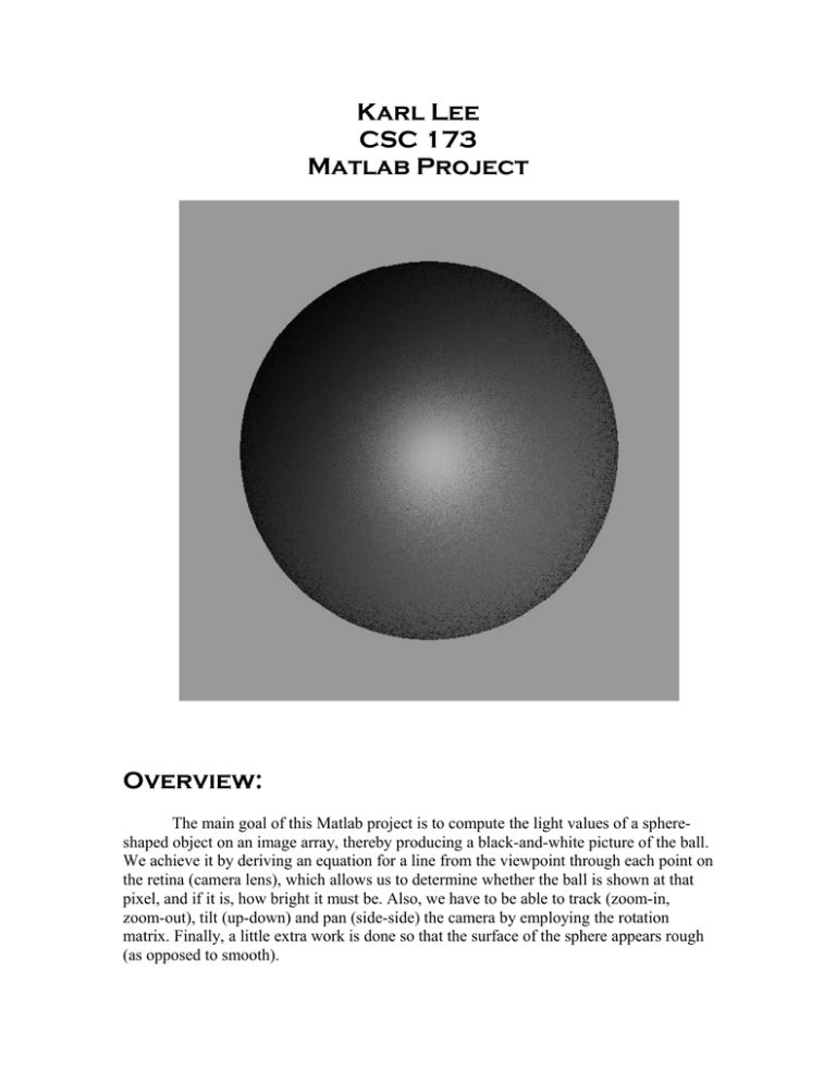
Karl Lee CSC 173 Matlab Project Overview: The main goal of this Matlab project is to compute the light values of a sphereshaped object on an image array, thereby producing a black-and-white picture of the ball. We achieve it by deriving an equation for a line from the viewpoint through each point on the retina (camera lens), which allows us to determine whether the ball is shown at that pixel, and if it is, how bright it must be. Also, we have to be able to track (zoom-in, zoom-out), tilt (up-down) and pan (side-side) the camera by employing the rotation matrix. Finally, a little extra work is done so that the surface of the sphere appears rough (as opposed to smooth). Math Work: I assumed the view point to be at the origin (that is, (0, 0, 0)’) since this assumption makes math much easier. If x’, y’, and z’ denote the coordinate values of a point on the retina, then the line that goes through both the origin and the point is simply described by x = 0 + u (x’-0) = ux’ y = 0 + u (y’-0) = uy’ z = 0 + u (z’-0) = uz’, where u is a real number and (x,y,z)’ is a point on the line. A sphere at the point (x’’, y’’,z’’)’ with the radius r is expressed by the formula (x – x’’)2 + (y – y’’) 2 + (z – z’’) 2 = r2 where (x,y,z)’ is a surface point of the sphere. Thus we can plug the former x, y, and z values into the sphere formula to obtain an expression for u that tells us whether the ray line hits the sphere, and if so, where. After some juggling around with the variables, we end up with the following equation au2 + bu + c = 0 a = x’2 + y’2 + z’2 b = -2 ( x’x’’ + y’y’’ + z’z’’) c = x’’2 + y’’2 + z’’2 – r2 (notice that math is much simpler now that we have assumed the view point to be at the origin). So if the discriminant of u (that is , b2 – 4ac) is negative, we don’t have the intersection point. If it is equal to zero, the line intersects the sphere at exactly one point (i.e. at the rim). If it is greater than zero, the line penetrates the sphere to produce two intersection points. Anyhow, we just need the front points of the sphere for an image, so we can use the following formula for solving a quadratic equation u = (-b – sqrt(b2 – 4ac)) / 2a And plug the value of u into the description of x, y, and z to obtain the actual point coordinates of the surface points of the sphere. Programming: The programming part is a direct translation of the math work shown above. As said, my view point is at the origin, and I have put my retina array “at the center” (i.e. the retina’s center point has zero x and y values), faithfully following CB’s suggestion. I have also implemented the specular reflection part beyond a mere Lambertain surface, and the math gets a little more complex. Basically, the idea is that we want to amplify the light values of the parts where the light is shed, so that they appear even brighter, and reduce the light values of the parts where the light is less shed, so that they appear darker. This strategy is done by exponentiating normalized values. The result gives a much nicer-looking, mirror-like ball shape. My example ball sphere1 is centered at (0,0,400)’ with radius 300. Using a 600 by 600 retina at z = 100, we an image like this with the light shown from (-1,1,-1)’ (remember that this is the direction toward the light source) With the light vector (0,0,-1) and (-1,-4,-6), we obtain, respectively, Camera Work: In order to tilt the camera, we just need to rotate the retina array around the y-axis (that is, in the LAB system). Likewise, in order to pan the camera, we just need to rotate the retina array around the x-axis. To implement this, we just have to multiply the coordinate vectors of the retina by the corresponding rotation matrix, whose math is given in the code. The image of the same example (sphere1, first light source), when tilted, panned, tilted and panned, now looks Note that distortion is strong because the sphere is too close to the camera lens. Therefore, when I make a new sphere, sphere2, with the center point further away at (0,0,1000)’, the image of sphere2 is less distorted when tilted or panned, as shown below Finally, in order to track (or zoom), we just add a scalar to each x, y, and z coordinate value. The following is an image resulting from zooming in by 100 onto sphere1 . Extra: In order to make the surface appear rough, all we have to do is to perturb the surface normal vectors by some random value. I just multiplied the coordinates of the normal vector by a random value between 0.5 and 1.5 (the lines are commented out in the actual code), and the resulting images for sphere1 and zoomed-in sphere2 (and, of course, the cover image) are given below They look like candies. Merry Christmas! -Karl Lee


