I2C IO Expansion Hardware Compatibility 1.
advertisement
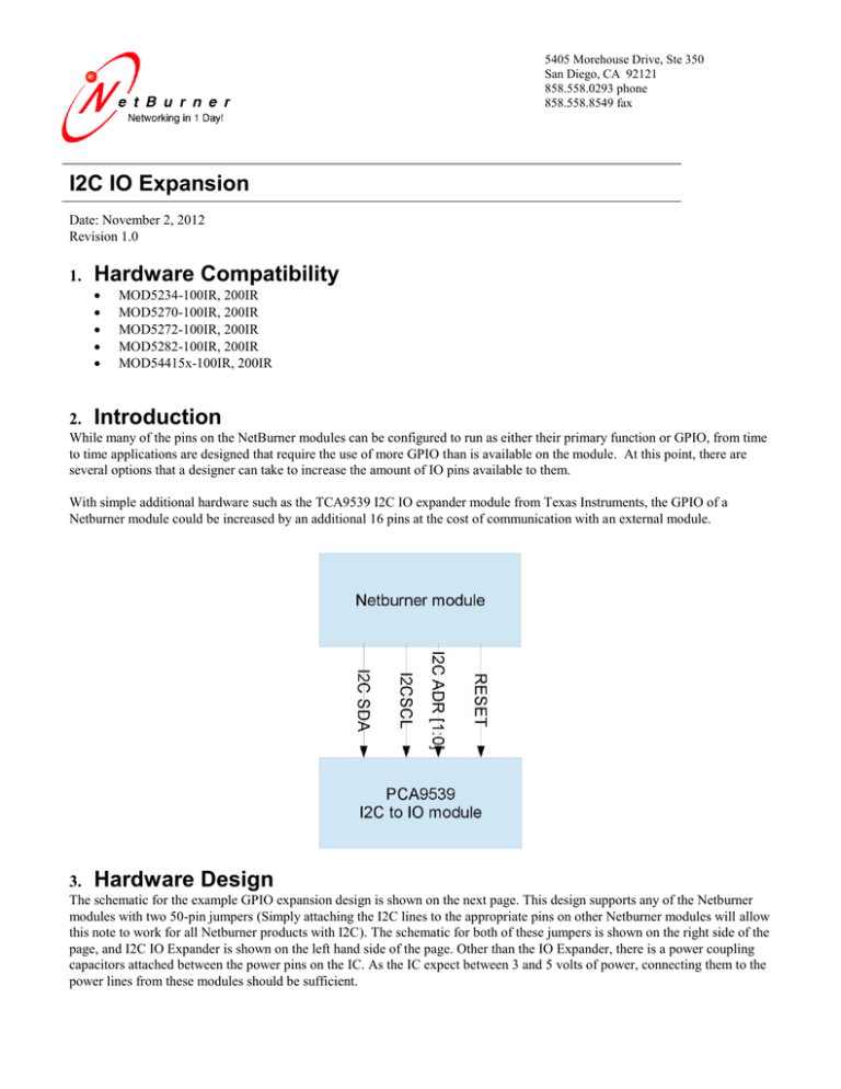
5405 Morehouse Drive, Ste 350 San Diego, CA 92121 858.558.0293 phone 858.558.8549 fax I2C IO Expansion Date: November 2, 2012 Revision 1.0 1. Hardware Compatibility 2. MOD5234-100IR, 200IR MOD5270-100IR, 200IR MOD5272-100IR, 200IR MOD5282-100IR, 200IR MOD54415x-100IR, 200IR Introduction While many of the pins on the NetBurner modules can be configured to run as either their primary function or GPIO, from time to time applications are designed that require the use of more GPIO than is available on the module. At this point, there are several options that a designer can take to increase the amount of IO pins available to them. With simple additional hardware such as the TCA9539 I2C IO expander module from Texas Instruments, the GPIO of a Netburner module could be increased by an additional 16 pins at the cost of communication with an external module. 3. Hardware Design The schematic for the example GPIO expansion design is shown on the next page. This design supports any of the Netburner modules with two 50-pin jumpers (Simply attaching the I2C lines to the appropriate pins on other Netburner modules will allow this note to work for all Netburner products with I2C). The schematic for both of these jumpers is shown on the right side of the page, and I2C IO Expander is shown on the left hand side of the page. Other than the IO Expander, there is a power coupling capacitors attached between the power pins on the IC. As the IC expect between 3 and 5 volts of power, connecting them to the power lines from these modules should be sufficient. 4. Bill of Material Used ==== 1 1 Part Type ======================= 0.01uF Cap I2C GPIO Expander Designator ========== C1 TCA9539 Vendor ================== DIGIKEY DIGIKEY Part Number Description ======================== =========================== BC2662TB-ND CAP 10000pF 50V 296-25130-2-ND IC I/O EXPANDER I2C 16B TSSOP 5. Software Drivers 5.1. Functionality Essentially, the additional hardware works with the processor by sending messages to the I2C module which controls the additional GPIO lines. It should be noted that if even more GPIO lines should be necessary, Texas Instruments does have another module available which would increase the number of I/O pins by 24 (see TCA6424A through ti.com or another source). What this means is that to use the expanded GPIO one simply needs an understanding of the I2C protocol. For a review of this protocol, simply see one of the following links or see the datasheet for the TCA 9539. 5.2. I2C Links http://en.wikipedia.org/wiki/I%C2%B2C – Wikipedia article http://www.robot-electronics.co.uk/acatalog/I2C_Tutorial.html - a fairly detailed tutorial from a hobbyist site http://www.ti.com/lit/ds/symlink/tca9539.pdf - Datasheet for TCA9359 5.3. Explanation of Included Driver Attached with this document is an included driver in the form of a header and cpp file that uses the I2C protocol to communicate with the module. The following notes should be taken into consideration when using the driver. 1. The address for the module is given as diagrammed in the schematic above. The TCA9539 includes 2 address lines that are user setable allowing the use of multiple instances of the same module and further expansion of the number of I/O ports available with up to 4 TCA9539 modules. To communicate with multiple instances of this IC, simple modify the header files to communicate with different I2C addresses. 2. As written, the header files only allow for single port communication. The header files here were written for demonstration purposes and can be modified to change or read multiple IO lines with the same instruction. For more information about this, it is recommended that the user consult the datasheet available above.
