EE210 Mark Randall Lab 7
advertisement
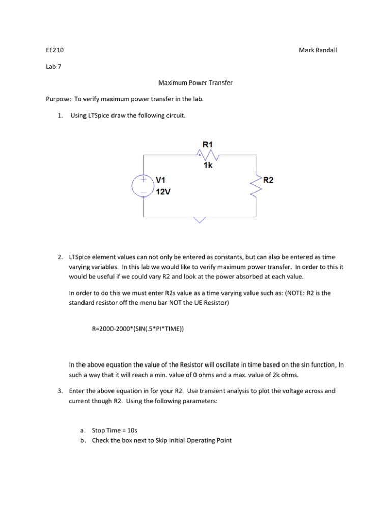
EE210 Mark Randall Lab 7 Maximum Power Transfer Purpose: To verify maximum power transfer in the lab. 1. Using LTSpice draw the following circuit. 2. LTSpice element values can not only be entered as constants, but can also be entered as time varying variables. In this lab we would like to verify maximum power transfer. In order to this it would be useful if we could vary R2 and look at the power absorbed at each value. In order to do this we must enter R2s value as a time varying value such as: (NOTE: R2 is the standard resistor off the menu bar NOT the UE Resistor) R=2000-2000*(SIN(.5*PI*TIME)) In the above equation the value of the Resistor will oscillate in time based on the sin function, In such a way that it will reach a min. value of 0 ohms and a max. value of 2k ohms. 3. Enter the above equation in for your R2. Use transient analysis to plot the voltage across and current though R2. Using the following parameters: a. Stop Time = 10s b. Check the box next to Skip Initial Operating Point 4. You should now have a graph that has both the current through and voltage across R2. Using P=IV we can now plot the Power absorbed by the device. Right click on the graph and select add Trace. Select the Voltage that corresponds to the voltage across R2 and the current through it and add the correct Expression in the box. Click OK. a. (Vn001) * IR2 5. Now use the curser to find the time at which the absorbed power is maximized. Use this Time value to calculate the value of R2 for maximum power transfer. Does this value correspond to what you expect?
