Anode Catalyst Development for Polymer Electrolyte Membrane Fuel Cells Noramalina Mansor
advertisement
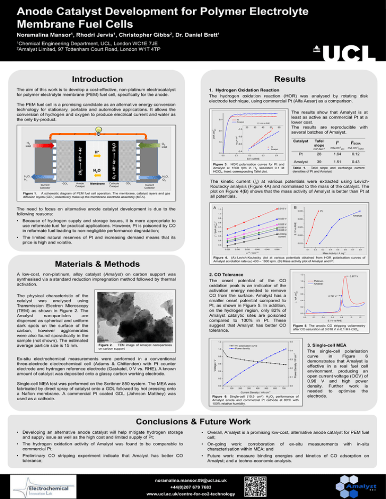
Anode Catalyst Development for Polymer Electrolyte Membrane Fuel Cells Noramalina Mansor1, Rhodri Jervis1, Christopher Gibbs2, Dr. Daniel Brett1 1Chemical Engineering Department, UCL, London WC1E 7JE 2Amalyst Limited, 97 Tottenham Court Road, London W1T 4TP Results Introduction e- e- e- e- ee- e- Current Collector Anode Catalyst 2.0 H2O Membrane E / mV vs RHE 20 30 40 50 60 -1.6 Catalyst j0ECSA mV dec-1 mA cm-2geo mA cm-2ECSA Pt 28 1.64 0.12 Amalyst 39 1.51 0.43 Pt Amalyst -2.4 0.0 Cathode Catalyst Tafel slope j0 -2.0 0.0 H2O, H2 GDL 2H2O H+ -1.2 1.0 O2 inlet 0.1 0.2 0.3 0.4 E/V vs RHE O2 + 4H+ 4e- 2H2 4H+ + 4e- H2 inlet Pt Amalyst The results show that Amalyst is at least as active as commercial Pt at a lower cost. The results are reproducible with several batches of Amalyst. Figure 3. HOR polarisation curves for Pt and Amalyst at 1600 rpm in H2 saturated 0.1 M HClO4. Inset: corresponding Tafel plot. H2O, O2 GDL Table 1. Tafel slope and exchange current densities of Pt and Amalyst The kinetic current (ik) at various potentials were extracted using LevichKoutecky analysis (Figure 4A) and normalised to the mass of the catalyst. The plot on Figure 4(B) shows that the mass activity of Amalyst is better than Pt at all potentials. Current Collector Figure 1. A schematic diagram of PEM fuel cell operation. The membrane, catalyst layers and gas diffusion layers (GDL) collectively make up the membrane electrode assembly (MEA). A The need to focus on alternative anode catalyst development is due to the following reasons: B 0.015 V 1.1 Pt 0.035 1.0 Amalyst 0.9 -1 j / (mA cm ) -2 -1 geo • Because of hydrogen supply and storage issues, it is more appropriate to use reformate fuel for practical applications. However, Pt is poisoned by CO in reformate fuel leading to non-negligible performance degradation; • The limited natural reserves of Pt and increasing demand means that its price is high and volatile. 0.020 V 0.8 0.030 E / V vs RHE e- 3.0 j/mA cm-2 geo The PEM fuel cell is a promising candidate as an alternative energy conversion technology for stationary, portable and automotive applications. It allows the conversion of hydrogen and oxygen to produce electrical current and water as the only by-product. 1. Hydrogen Oxidation Reaction The hydrogen oxidation reaction (HOR) was analysed by rotating disk electrode technique, using commercial Pt (Alfa Aesar) as a comparison. log jk/A cm-2 The aim of this work is to develop a cost-effective, non-platinum electrocatalyst for polymer electrolyte membrane (PEM) fuel cell, specifically for the anode. 0.025 V 0.7 0.030 V 0.035 V 0.6 Limiting current 0.5 0.025 0.020 0.4 0.015 0.3 0.025 0.030 0.035 0.040 0.045 0.050 0.1 0.2 -1/2 / rpm-1/2 0.4 0.5 0.6 0.7 0.8 Mass Activity / A mg-1 Figure 4. (A) Levich-Koutecky plot at various potentials obtained from HOR polarisation curves of Amalyst at rotation rate (ω) 400 – 1600 rpm. (B) Mass activity plot of Amalyst and Pt. 2. CO Tolerance The onset potential of the CO oxidation peak is an indicator of the activation energy needed to remove CO from the surface. Amalyst has a smaller onset potential compared to Pt, as shown in Figure 5. In addition, on the hydrogen region, only 82% of Amalyst catalytic sites are poisoned compared to 100% in Pt. These suggest that Amalyst has better CO tolerance. 1.2 Figure 2. TEM image of Amalyst nanoparticles on carbon support 1.2 0.8 Voltage / V 0.6 0.797 V 0.4 0.2 0.0 0.0 0.2 0.4 0.6 0.8 1.0 1.2 E / V vs RHE Figure 5. The anodic CO stripping voltammetry after CO saturation at 0.018 V in 0.1 M HClO4. V-I polarisation curve Power density 0.4 0.8 0.3 0.6 0.2 0.4 0.1 0.2 Single-cell MEA test was performed on the Scribner 850 system. The MEA was fabricated by direct spray of catalyst onto a GDL followed by hot pressing onto a Nafion membrane. A commercial Pt coated GDL (Johnson Matthey) was used as a cathode. Platinum Amalyst 0.5 1.0 Ex-situ electrochemical measurements were performed in a conventional three-electrode electrochemical cell (Adams & Chittenden) with Pt counter electrode and hydrogen reference electrode (Gaskatel, 0 V vs. RHE). A known amount of catalyst was deposited onto a glassy carbon working electrode. 0.877 V 1.0 j / mA cm-2 geo A low-cost, non-platinum, alloy catalyst (Amalyst) on carbon support was synthesised via a standard reduction impregnation method followed by thermal activation. 0.0 Power Density / W cm-2 Materials & Methods The physical characteristic of the catalyst was analysed using Transmission Electron Microscopy (TEM) as shown in Figure 2. The Amalyst nanoparticles are dispersed as spherical and uniform dark spots on the surface of the carbon, however agglomerates were also found sporadically in the sample (not shown). The estimated average particle size is 15 nm. 0.3 0.0 0 100 200 300 400 500 600 700 Current Density / mA cm-2 Figure 6. Single-cell (10.9 cm2) H2/O2 performance of Amalyst anode and commercial Pt cathode at 80oC with 100% relative humidity. 3. Single-cell MEA The single-cell polarisation curve in Figure 6 demonstrates that Amalyst is effective in a real fuel cell environment, producing an open current voltage (OCV) of 0.96 V and high power density. Further work is needed to optimise the electrode. Conclusions & Future Work • Developing an alternative anode catalyst will help mitigate hydrogen storage and supply issue as well as the high cost and limited supply of Pt; • Overall, Amalyst is a promising low-cost, alternative anode catalyst for PEM fuel cell; • The hydrogen oxidation activity of Amalyst was found to be comparable to commercial Pt; • On-going work: corroboration characterisation within MEA; and • Preliminary CO stripping experiment indicate that Amalyst has better CO tolerance; • Future work: measure binding energies and kinetics of CO adsorption on Amalyst; and a techno-economic analysis. noramalina.mansor.09@ucl.ac.uk +44(0)207 679 7683 www.ucl.ac.uk/centre-for-co2-technology of ex-situ measurements with in-situ


