Development of Graphitic-Carbon Nitride as Catalyst
advertisement
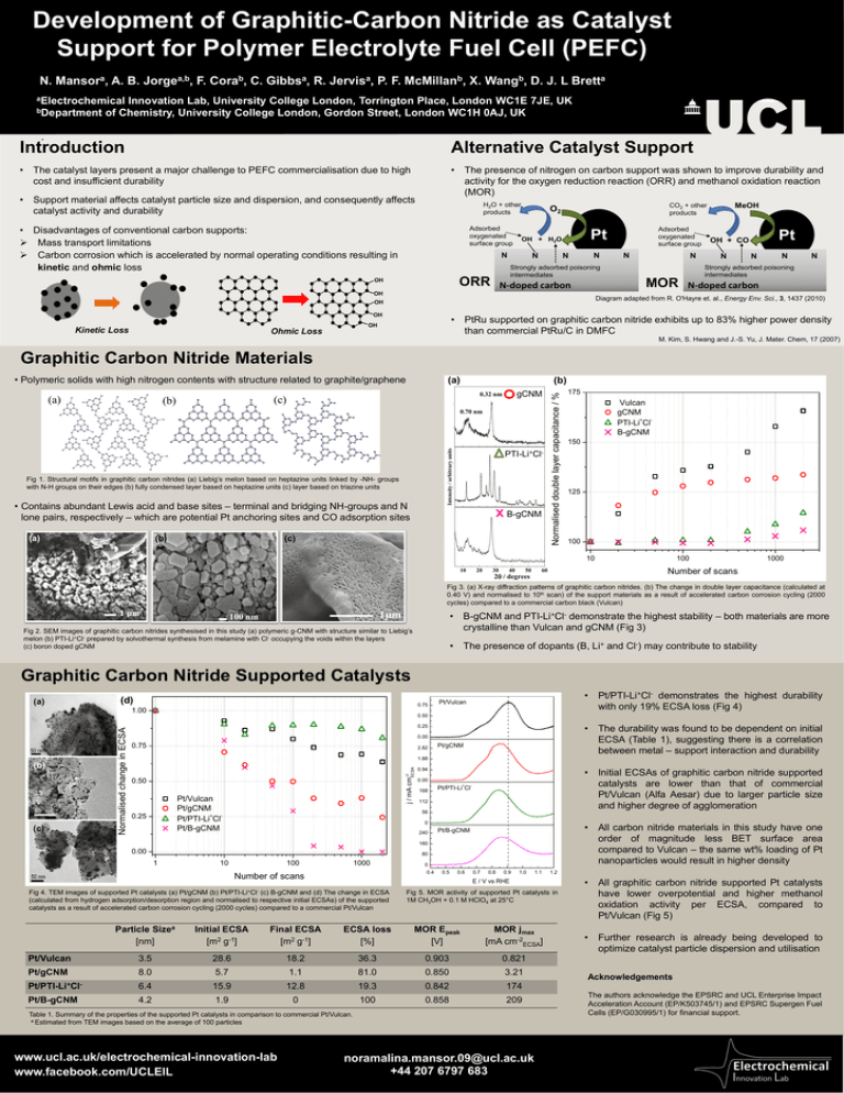
Development of Graphitic-Carbon Nitride as Catalyst Support for Polymer Electrolyte Fuel Cell (PEFC) N. Mansora, A. B. Jorgea,b, F. Corab, C. Gibbsa, R. Jervisa, P. F. McMillanb, X. Wangb, D. J. L Bretta aElectrochemical Innovation Lab, University College London, Torrington Place, London WC1E 7JE, UK bDepartment of Chemistry, University College London, Gordon Street, London WC1H 0AJ, UK . Introduction Alternative Catalyst Support • The catalyst layers present a major challenge to PEFC commercialisation due to high cost and insufficient durability • The presence of nitrogen on carbon support was shown to improve durability and activity for the oxygen reduction reaction (ORR) and methanol oxidation reaction (MOR) • Support material affects catalyst particle size and dispersion, and consequently affects catalyst activity and durability H2O + other products • Disadvantages of conventional carbon supports: Mass transport limitations Carbon corrosion which is accelerated by normal operating conditions resulting in kinetic and ohmic loss Adsorbed oxygenated surface group N N Strongly adsorbed poisoning intermediates ORR OH N N-doped carbon OH OH N MOR N N N N Strongly adsorbed poisoning intermediates N-doped carbon • PtRu supported on graphitic carbon nitride exhibits up to 83% higher power density than commercial PtRu/C in DMFC OH Ohmic Loss N Pt OH + CO Diagram adapted from R. O'Hayre et. al., Energy Env. Sci., 3, 1437 (2010) OH Kinetic Loss Adsorbed oxygenated surface group Pt OH + H2O N MeOH CO2 + other products O2 M. Kim, S. Hwang and J.-S. Yu, J. Mater. Chem, 17 (2007) Graphitic Carbon Nitride Materials Intensity / arbitrary units (c) (b) Intensity / arbitrary units Intensity / arbitrary units (a) (a) Fig 1. Structural motifs in graphitic carbon nitrides (a) Liebig’s melon based on heptazine units linked by -NH- groups with N-H groups on their edges (b) fully condensed layer based on heptazine units (c) layer based on triazine units • Contains abundant Lewis acid and base sites – terminal and bridging NH-groups and N lone pairs, respectively – which are potential Pt anchoring sites and CO adsorption sites (a) (b) (c) (b) gCNM 0.32 nm 0.70 nm 10 10 20 20 30 40 50+ 2degrees 60 PTI-Li Cl- x2 B-gCNM degrees 30 40 50 60 Normalised double layer capacitance / % • Polymeric solids with high nitrogen contents with structure related to graphite/graphene 175 Vulcan gCNM PTI-Li+ClB-gCNM 150 125 100 10 10 20 30 40 50 100 1000 Number of scans 60 2 / degrees Fig 3. (a) X-ray diffraction patterns of graphitic carbon nitrides. (b) The change in double layer capacitance (calculated at 0.40 V) and normalised to 10th scan) of the support materials as a result of accelerated carbon corrosion cycling (2000 cycles) compared to a commercial carbon black (Vulcan) • B-gCNM and PTI-Li+Cl- demonstrate the highest stability – both materials are more crystalline than Vulcan and gCNM (Fig 3) 100 nm Fig 2. SEM images of graphitic carbon nitrides synthesised in this study (a) polymeric g-CNM with structure similar to Liebig’s melon (b) PTI-Li+Cl- prepared by solvothermal synthesis from melamine with Cl- occupying the voids within the layers (c) boron doped gCNM • The presence of dopants (B, Li+ and Cl-) may contribute to stability Graphitic Carbon Nitride Supported Catalysts (a) (d) 0.75 (c) Pt/Vulcan 0.50 • The durability was found to be dependent on initial ECSA (Table 1), suggesting there is a correlation between metal – support interaction and durability 0.25 0.00 0.75 2.82 Pt/gCNM 1.88 j / mA cm-2 ECSA (b) Normalised change in ECSA 1.00 • Pt/PTI-Li+Cl- demonstrates the highest durability with only 19% ECSA loss (Fig 4) 0.50 Pt/Vulcan Pt/gCNM Pt/PTI-Li+ClPt/B-gCNM 0.25 • Initial ECSAs of graphitic carbon nitride supported catalysts are lower than that of commercial Pt/Vulcan (Alfa Aesar) due to larger particle size and higher degree of agglomeration 0.94 0.00 168 Pt/PTI-Li+Cl- 112 56 0 240 • All carbon nitride materials in this study have one order of magnitude less BET surface area compared to Vulcan – the same wt% loading of Pt nanoparticles would result in higher density Pt/B-gCNM 160 0.00 80 1 10 100 1000 0 0.4 Number of scans 0.5 0.6 0.7 0.8 0.9 1.0 1.1 E / V vs RHE Pt/PTI-Li+Cl- Fig 4. TEM images of supported Pt catalysts (a) Pt/gCNM (b) (c) B-gCNM and (d) The change in ECSA (calculated from hydrogen adsorption/desorption region and normalised to respective initial ECSAs) of the supported catalysts as a result of accelerated carbon corrosion cycling (2000 cycles) compared to a commercial Pt/Vulcan Fig 5. MOR activity of supported Pt catalysts in 1M CH3OH + 0.1 M HClO4 at 25°C Particle Sizea [nm] Initial ECSA [m2 g-1] Final ECSA [m2 g-1] ECSA loss [%] MOR Epeak [V] MOR jmax [mA cm-2ECSA] Pt/Vulcan 3.5 28.6 18.2 36.3 0.903 0.821 Pt/gCNM 8.0 5.7 1.1 81.0 0.850 3.21 Pt/PTI-Li+Cl- 6.4 15.9 12.8 19.3 0.842 174 Pt/B-gCNM 4.2 1.9 0 100 0.858 209 Table 1. Summary of the properties of the supported Pt catalysts in comparison to commercial Pt/Vulcan. a Estimated from TEM images based on the average of 100 particles Collaborators logos www.ucl.ac.uk/electrochemical-innovation-lab www.facebook.com/UCLEIL 1.2 noramalina.mansor.09@ucl.ac.uk +44 207 6797 683 • All graphitic carbon nitride supported Pt catalysts have lower overpotential and higher methanol oxidation activity per ECSA, compared to Pt/Vulcan (Fig 5) • Further research is already being developed to optimize catalyst particle dispersion and utilisation Acknowledgements The authors acknowledge the EPSRC and UCL Enterprise Impact Acceleration Account (EP/K503745/1) and EPSRC Supergen Fuel Cells (EP/G030995/1) for financial support.
