From: AAAI Technical Report SS-03-02. Compilation copyright © 2003, AAAI (www.aaai.org). All rights reserved.
Manufacturability-Driven Spatial Partitioning:
A Systematic Approach to Computational Shape Synthesis in Manufacturing Applications
Satyandra K. Gupta and Jun Huang
Mechanical Engineering Department and Institute for Systems Research
University of Maryland
College Park, MD 20742
Abstract
Quite often complex shapes are not manufacturable as
a single component. Due to manufacturing constraints,
the desired complex object needs to be partitioned into
a number of smaller and simpler manufacturable
components.
After
manufacturing
individual
components, the complex object is realized by
assembling various components together. Therefore,
spatial-partitioning can be used to perform shape
synthesis of manufacturable objects in many
applications. This paper describes a systematic
approach to solving the general manufacturabilitydriven spatial partitioning problem that arises in
various types of manufacturing processes due to tool
accessibility problems. The approach described in this
paper has been used successfully to automatically
synthesize shapes of multi-piece permanent molds,
multi-piece sacrificial molds, and multi-stage molds
for making multi-material parts.
Introduction
Quite often complex objects are not manufacturable as a
single component. Due to manufacturing constraints, the
desired complex object needs to be partitioned into a
number of smaller and simpler manufacturable
components. After manufacturing individual components,
the complex object is realized by assembling various
components together. We refer to such partitioning
practices as manufacturability-driven spatial partitioning.
The range of industrial applications where
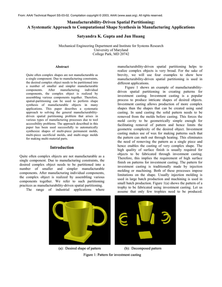
(a): Desired shape of pattern
manufacturability-driven spatial partitioning helps to
realize complex objects is very broad. For the sake of
brevity, we will use four examples to show how
manufacturability-driven spatial partitioning is used in
different applications.
Figure 1 shows an example of manufacturabilitydriven spatial partitioning in creating patterns for
investment casting. Investment casting is a popular
process to produce intricate shapes of desired objects.
Investment casting allows production of more complex
shapes than the shapes that can be created using sand
casting. In sand casting the solid pattern needs to be
removed from the molds before casting. This forces the
mold cavity to be geometrically simple enough for
facilitating removal of pattern and hence limits the
geometric complexity of the desired object. Investment
casting makes use of wax for making patterns such that
the pattern can melt out through heating. This eliminates
the need of removing the pattern as a single piece and
hence enables the casting of very complex shape. The
high quality of surface finish is usually required for
objects to be fabricated through investment casting.
Therefore, this implies the requirement of high surface
finish on patterns for investment casting. The pattern for
investment casting is traditionally made by injection
molding or machining. Both of these processes impose
limitations on the shape. Usually injection molding is
used in large batch production and machining is used in
small batch production. Figure 1(a) shows the pattern of a
trophy to be fabricated using investment casting. Let us
assume that only few trophies need to be produced.
(b): Decomposed pattern
Figure 1: Pattern for investment casting
(a): Part to
be molded
(b): Desired shape of mold
(c): Decomposed mold
Figure 2: Mold for sacrificial mold casting
Therefore machining is the preferred method for creating
the casting. Since the shape of trophy is geometrically
complex, the pattern cannot be realized as a single
component. Figure 1(b) shows a candidate partitioning of
the shape such that the shape of every component can be
realized through either milling or turning. The entire
shape of the pattern can be obtained by assembling
together all the machined components.
Figure 2 shows an example of manufacturabilitydriven spatial partitioning in creating molds for
gelcasting. Gelcasting is emerging as a popular method
for making high performance ceramic parts for a wide
variety of aerospace, automotive, and industrial
applications. Gelcasting can be used to produce
geometrically complex parts. Low pouring temperatures
in gelcasting enable use of sacrificial molds. Furthermore,
green parts need not be extracted from sacrificial molds
before sintering. Sacrificial molds containing green parts
can be directly put into sintering ovens. The sintering
process melts the sacrificial molds and sinters the green
part, and therefore eliminates potential problems that
result from handling green ceramic parts. Figure 2(a)
shows a ceramic rotor. Figure 2(b) shows the cavity of the
sacrificial mold to produce the rotor. Designing the mold
assembly for this cavity is not a trivial task. Simply
dividing the mold shape into two halves may result in
(a): Desired shape of housing
unmach inable mold component(s) – the acute angle
between the blades and the end face in the cavity makes
regions in at least one component inaccessible to any
cutting tool in 3-axis machining. Figure 2(c) shows a
candidate partitioning of the mold shape such that each
component is completely accessible to cutting tool and
hence manufacturable individually. These components
form a feasible mold assembly.
Figure 3 shows the manufacturability-driven spatial
partitioning in sheet-metal product design. Products made
by sheet-metal bending are extensively used in everyday
life, including from metal furniture, appliances, to car
bodies and aircraft fuselages. Primarily there are two
possible reasons leading to the product shape not being
able to be realized through bending from a single sheet of
metal. First, the shape of the product cannot be unfolded
into a single 2D blank. Second, some desired bends are
not accessible to tools [Wang 1997]. Therefore, products
may have to be realized as assemblies of components
purely due to the above manufacturability reasons. The
sheet-metal housing shown in Figure 3(a) cannot be
produced from a single sheet because some bends are not
accessible to the punch. Figure 3(b) shows that the shape
of the housing can be partitioned into four bendable
components. The housing can be realized by assembling
the four components through welding or other techniques.
(b): Decomposed housing
Figure 3: Sheet-metal housing
(a): Desired shape of rotor
(it includes support material)
(b): Decomposed rotor
(it includes support material)
Figure 4: Shape deposition manufacturing
Figure 4 shows the manufacturability-driven spatial
partitioning in shape deposition manufacturing. Shape
deposition manufacturing (SDM) is a layered
manufacturing process in which parts are fabricated by
alternately depositing layers of part material and
sacrificial support material in a certain build orientation,
and machining each layer to give it three-dimensional
shape [Merz et. al. 1994]. In order to fabricate an object
through SDM, the shape of the object combined with the
sacrificial support material needs to be partitioned into
machinable layers. The reason a face is not machinable is
the presence of undercuts on it with respect to the given
build orientation. Figure 4 shows a rotor to be prototyped
by SDM. Figure 4(a) shows the combination of the shape
of the rotor and the support material. Figure 4(b) shows a
partitioning of the combination such that every layer is
machinable without undercut with respect to the build
orientation.
The above examples show some of the representative
industrial application domains, ranging from mold and die
machining, sheet metal products, to layered
manufacturing of ceramic and composite parts, where
spatial
partitioning
is
needed
for
various
manufacturability reasons.
It is becoming clear that manufacturability-driven
spatial partitioning is a general problem that process
planners and tool designers confront in many different
manufacturing applications. Although the detailed causes
for partitioning may differ from one manufacturing
application to another. There seem to be a small number
of fundamental constraints for each manufacturing
process that force the partitioning of object. This
observation gives us hope that the manufacturabilitydriven spatial partitioning problems can be solved through
a systematic approach if we can identify violation of
fundamental constraints and use them as a guide towards
synthesis of manufacturable shapes.
In order to develop the next generation CAD/CAM
systems we will need a computational approach to
automatically perform manufacturability-driven spatial
partitioning. Constraints and capabilities of many known
manufacturing processes have been well documented. By
examining these constraints and capabilities, we found
that although the detailed causes for partitioning may
differ from one manufacturing application to another,
there seem to be a small number of fundamental
constraints for each manufacturing process that force the
partitioning of object. This observation gives us hope that
the manufacturability-driven spatial problems can be
solved through a systematic approach if we can identify
violation of fundamental constraints and use them as a
guide towards partitioning. In order to automate process
planning and tool design, we are developing a systematic
approach to manufacturability-driven spatial partitioning.
Overview of Approach
This paper focuses on solving the manufacturabilitydriven spatial partitioning problem for material removal
processes. Material removal processes are those
manufacturing processes that remove material from a
work-piece stock to create the desired shape [Groover
1996]. In such processes, accessibility plays a dominant
role in determining manufacturability of an object.
Examples of such processes include the majority of
feature creation operations such as milling, turning,
electro-discharge machining, etc. In this paper, we
consider accessibility as the primary driver in
manufacturability-driven spatial partitioning. Therefore,
we will treat manufacturability-driven spatial partitioning
achieved by accessibility-based decomposition. In
order to alleviate accessibility problems, we need to
identify feasible partitioning of object that can
alleviate accessibility problems. Since the solution
space is infinite, we need ways to distinguish
promising non-dominated solutions from dominated
solutions. There may exist multiple partitioning
solutions by which we can achieve the goal of
eliminating inaccessibility. Some of them may be
preferable over others from the manufacturing cost
point-of-view. For example, solutions that result in
simpler assemblies are usually preferable because a
simpler assembly usually means lower manufacturing
cost. Selection of a set of partitioning planes in a
solution space is a combinatorial optimization
problem and believed to be intractable. The next
section describes an algorithm for solving this
combinatorial
optimization
problem
during
generation of sacrificial multi-piece molds.
as an accessibility-driven spatial partitioning problem.
Our approach consists of the following three steps. First,
we will model accessibility constraints of various material
removal processes as geometric constraints and provide
algorithms for detecting violations of these geometric
constraints in the object to be produced. Second, in order
to eliminate these violations in the entire object, we will
provide algorithms for partitioning the object into a set of
components such that each of them is individually free of
accessibility problems and therefore manufacturable.
Third, we will provide algorithms for adding assembly
features that constrain the unnecessary relative degrees of
freedom among the manufactured components and
facilitate easy assembly.
Solving accessibility-driven spatial partitioning for a
particular manufacturing application requires addressing
the following research issues:
•
•
Accessibility Analysis. An object needs to be
partitioned into smaller components to facilitate its
manufacturing if it is not completely accessible to a
tool. In order to detect whether a partitioning is
needed due to accessibility problems, we need to
perform accessibility analysis on the given object.
Accessibility information can be represented in many
different ways. However, since we are interested in
using accessibility information for partitioning the
object, we need representations that can support
efficient partitioning of objects. Boundary of objects
consists of infinite number of points. Therefore, it
will be computationally intractable to explicitly store
accessibility of every point. We have developed a
finite representation that includes information to help
in partitioning the object. In some cases, is not
possible to efficiently compute accessibility exactly.
In such cases a trade-of needs to be made between
accuracy and efficiency. Furthermore, when
approximation is inevitable, we should have
algorithms that result in errors on the safer side. For
example, an approximation error that results in an
accessible object to be classified inaccessible might
not be acceptable because it would cause additional
partitioning but still result in a feasible solution. On
the other hand, an approximation error that results in
an inaccessible object to be classified as accessible
object is unacceptable because it would not do the
necessary partitioning and therefore result in objects
that are not manufacturable. The next section
describes algorithms to compute accessibility
attributes for solving the partitioning problem for
generating sacrificial multi-piece molds.
Accessibility-Based Decomposition. Once an object
has been found not to manufacturable due to
accessibility reasons, we need to partition it to
eliminate inaccessibility on the object. This can be
•
Addition of Assembly Features. After each
component of the desired object resulting from the
spatial partitioning has been created individually, we
need to add assembly features to them to
kinematically constrain them and facilitate easy
assembly. In order to determine where to add
assembly features, we need to find a way to represent
the kinematic state of various subassemblies in the
assembly. For a single component, its degree of
freedom is a good description of its kinematical state.
But it is not an adequate description for
subassemblies. Therefore we need a new
representation to describe kinematic state of an
assembly and its subassemblies. An ideal distribution
of assembly features would result in each component
neither under-constrained nor over-constrained.
Under-constraining allows undesirable relative
motions among components. Over-constraining, on
the other hand, would increase the manufacturing
cost and even lead to problems during physical
assembly. The next section describes algorithms for
solving this problem during generation of sacrificial
multi-piece molds.
Generating Sacrificial Multi-Piece Molds
Using Spatial Partitioning
This section describes how the general approach
described in the previous section can be used to designing
sacrificial multi-piece molds. Multi-piece molds refer to
molds having more than one parting surface and hence
more than two components. These molds can produce
complex parts that cannot be made using two-piece
molds. Since they have more than one parting surface,
they can be decomposed along different directions and
thus can be used to make geometrically complex parts.
Sacrificial molds refer to molds that can be destroyed
after the part has been produced. They are generally made
of low melting point materials such as wax or ABS and
are typically destroyed by heating the mold-part
assembly. Moreover, the wax molds can be easily
machined making them very easy to manufacture at high
production rates. Therefore, sacrificial molds can be used
to circumvent the disassembly problems that arise in use
of permanent molds. Sacrificial multi-piece molds find
use in a number of manufacturing domains. Examples
include manufacture of polymer parts and gelcasting of
ceramic parts
Unlike permanent molds where disassembly
considerations drive the mold decomposition, in case of
sacrificial molds primary considerations that drive the
mold decomposition are manufacturability of individual
mold components. CNC machining provides very good
surface finish on the mold components without requiring
any post-processing. Unfortunately both for ABS and
wax, electro-discharge machining does not work due to
poor conductivity of these materials. Therefore, we use
milling and drilling processes for making mold
components. In order to be machinable, the boundary of
mold components needs to be accessible to cutting tool.
Therefore, accessibility drives the mold decomposition
process in design of sacrificial molds.
We first construct gross shape of the mold by
subtracting the part model from the mold enclosure and
analyze its accessibility. Initially, the entire cavity inside
the gross shape of mold is inaccessible and therefore
cannot be machined. The gross mold shape is partitioned
using accessibility information. Each partitioning
improves accessibility and we eventually produce a set of
mold components that are accessible and therefore can be
produced using milling operations.
The input to the multi-piece sacrificial mold design
problem is:
1) A facet-based boundary representation of the gross
mold shape M of a desired object O. (The gross mold
shape M can be formed by subtracting O from the
desired mold enclosure.)
2) Index of faces Fnp on M that cannot be partitioned.
(Quite often in manufacturing applications, the
continuity of certain faces on objects is important
from functionality point-of-view and therefore their
corresponding faces on the molds cannot be
partitioned.)
If at least one facet on the boundary M is inaccessible, the
accessibility-driven partitioning algorithm will be used to
decompose M into a set A = {c1, c2, …, cN} of
components, each
represented by its boundary
representation, such that the following conditions are
satisfied:
1) Each ci∈A is a connected point set;
N
2) M =
Uc ;
i
i =1
3) Boundary of each ci∈A is completely accessible.
Currently we impose the following restrictions on the
accessibility-driven spatial partitioning problem:
1) The gross mold shape is partitioned only along
infinite planes.
2) Partitioning will be performed in a sequence and
associated with a particular intermediate solid model
in the sequence.
When alternative decompositions are possible, the
algorithm will need to select a decomposition that
minimizes the manufacturing cost associated with the
decomposition. In this paper this objective is modeled as
the minimum number of partitioning planes.
In addition, assembly features are added to eliminate
undesired relative degrees of freedom among the
components and facilitate the easy assembly of them to
realize the desired gross shape of the mold M.
Our approach to solving accessibility-based
decomposition problem for generating multi-piece
sacrificial molds includes the following steps.
1) Generate Accessibility Matrix: The first step is to
generate accessibility matrix for M. We use an
accessibility matrix to represent global accessibility
cones. In this scheme, the boundary of the unit sphere
is partitioned into a finite number of spherical
triangles, each representing a set of directions.
Accessibility matrix is defined in the following
manner. Rows of this matrix represent spherical
triangles. Columns of this matrix represent various
facets. Various entries in the matrix describe whether
a facet is accessible from a spherical triangle or not.
In addition, if ith spherical triangle resides within the
visibility map of jth facet, entry that corresponds to ith
row and jth column is filled with the index of the
facet(s) which is blocking jth facet from the directions
represented by ith spherical triangle. Details on how
to compute accessibility matrix are described in
[Dhaliwal et. al. 2000].
2) Preprocessing accessibility information: In this step,
we extract the blocking relationships among facets
from the accessibility matrix generated through
accessibility analysis. The facet-wise accessibility
matrix generated by our accessibility analysis
approach described in the previous step needs to be
rearranged so as to facilitate the efficient
accessibility-based partitioning. Primarily, the
information we need to extract through rearranging is
the direct representation of the blocking relationships
among various facets.
3) Generating initial candidate partitioning planes: In
this step, we discretize the solution space and
generate a finite number of initial candidate planes
for partitioning the gross mold shape. The initial
candidate partitioning plane set includes two types of
planes: (a) the planes of the natural planar faces on
the original gross mold shape M before facetization;
(b) planes that are generated by sampling over the 3D space.
4) Evaluating initial candidate partitioning planes: In
this step, we evaluate the initial set of candidate
partitioning planes to find out their quality (how
partitions along these planes will improve the
accessibility of various facets on the boundary of the
gross mold shape, and the accessibility of how many
facets will be improved). The evaluation of candidate
partitioning planes is conducted based on the
classification of various facets with respect to these
planes. If the generated plane intersects any face in
Fnp, then the plane is considered invalid and rejected.
Each candidate partitioning plane is further evaluated
by the number of target facets for which it is a
feasible partitioning plane, and the number of target
facets for which it is a near-miss partitioning plane.
5) Locating additional partitioning planes in the vicinity
of initial candidate planes:
In this step, we
improve the candidate-partitioning plane set by
finding better partitioning planes in the vicinity of
initial candidate planes. A plane P* in the vicinity of
an initial candidate partitioning plane P is a better
candidate partitioning plane than P if the cardinality
of u, the set of target facets that will become
accessible due to the partitioning along P, is less than
the cardinality of u*, the set of target facets that will
become accessible due to the partitioning along P*. If
u* is a superset of u, then the candidate partitioning
plane set is updated and improved by replacing P
with P*. Otherwise, P* is inserted into the candidate
partitioning plane set.
6) State-space search to identify near-optimal
partitioning plane set: In this step, from the
candidate-partitioning plane set we select a set of
partitioning planes that alleviate the accessibility
problem for the gross mold shape. We use an
algorithm based on set-covering technique to
minimize the number of partitioning planes in the set
and get a partitioning solution. Our algorithm has the
following properties: given a reasonable length of
allowed running time, it guarantees to find the exact
optimal solution if the number of partitioning planes
in it is relative low (1 to 3), while it finds a good
quality solution if the optimal solution requires a
large number of cuts. This algorithm takes G, the set
of candidate partitioning planes, and N as input,
where N is the number of cuts up to which an exact
optimal solution is desired. Our algorithm for this
task consists of the following steps:
a.
b.
c.
Find a feasible solution using the following
greedy scheme. Pick a plane from the set of
candidate partitioning planes G one by one until
the selected set of planes solve the problem for
all facets. At each step pick a plane that solves
the accessibility problems for the maximum
number of remaining inaccessible facets.
Consider this solution as the current best
solution.
Use a breadth-first search to find a solution of
cardinality N or below. If feasible solutions of
cardinality N or below are found, then return up
to z of them, where z is a user-specified number.
They are the optimal solutions. The user can
choose one from the z alternative solutions that is
the best with respect to other engineering
criteria.
If breadth-first search fails to find a solution of
cardinality N or below, use depth-first branchand-bound search to improve the solution found
in Step (a) in the remaining available time. When
the time expires return the current-best solution.
7) Generation of partitioning sequence: In this step, we
enumerate all possible sequence from the final
partitioning plane set obtained by Step 6, and
evaluate each sequence based on the number of
components it will yield (components that have
already become accessible need not be further
partitioned). The sequence that results in the
minimum number of components is selected. Because
the cardinality of the final partitioning plane set is
usually not a very large number, possible
combinations involved in this enumerative approach
are still tractable.
8) Addition of Assembly features: In this step, following
the partitioning sequence a cut tree is generated in a
top-down manner. In general, each cut is associated
with a non-leaf node in the tree, and each pair of
resulted intermediate components is associated with a
(a): Part
(b): mold assembly
Figure 5: Example A
pair of sibling nodes with the cut node as their parent.
After determining the cut tree, the algorithm locates a
set of candidate contact patches to add assembly
features such that the assembly would have the
minimum possible number of unconstrained
translation directions, i.e., additional assembly
features will not help to reduce the number of
unconstrained translation directions. The number of
assembly features at each candidate contact patch is
also determined to eliminate relative rotational
degrees of freedom among components. After
determining the distribution of the features, in the
next step assembly features are created on the contact
patches. More details on this step can be found in
[Huang 2002].
More details on the above-described steps can be found in
[Huang and Gupta 2002]. We have tested this approach
on the automated mold design for several geometrically
complex parts. 1 to 3-cut solutions were generated for the
molds of these parts. Figure 5 and 6 show mold
assemblies for two parts generated using the algorithms
described in this paper.
(a): part
Conclusions
There are two fundamentally different ways to
computational shape synthesis. The first one is based on a
constructional approach where shapes are synthesized to
meet certain functional objectives. The second one is
based on a decompositional approach where the final
shape is known and it needs to be partitioned into smaller
and simpler components to realize it physically. Complex
engineering applications may require elements from both
approaches. This paper primarily focuses on
manufacturing applications requiring a decompostional
approach to shape synthesis.
We believe that developing a general framework for
expressing manufacturing constraints, and detecting
violation of these constraints will enable us to develop a
general approach to solving shape synthesis problem for a
wide variety of material removal processes. Based on our
experiences on accessibility-driven spatial partitioning
problem, the general approach to solving spatial
partitioning problem consists of the following four steps.
First, we need to model manufacturing constraints of
various manufacturing processes as geometric constraints.
Second, we need to develop algorithms for detecting
violations to these geometric constraints in the object to
(b): mold assembly
Figure 6: Example B
be produced. Third, we need to develop algorithms for
decomposing the object to eliminate these violations.
Finally, we need to develop algorithms for adding
assembly features to facilitate assembly of the
decomposed components to realize the original desired
object.
In addition to generating multi-piece sacrificial
molds, the general approach described in this paper has
been used successfully to automatically synthesize shapes
of multi-piece permanent molds and multi-stage molds for
making multi-material parts [Gupta et. al. 2002 and
Kumar and Gupta 2002].
The accessibility-driven spatial decomposition
approach presented in this paper can be extended in the
following areas to make it more comprehensive in nature:
1) Accessibility Analysis: Our current accessibility
analysis approach addresses the exact accessibility
cones only for polyhedral objects. This approach can
be extended by allowing projection of curved faces.
The approach to computing tool-based accessibility
cones currently only addresses ball-end tool
accessibility. Extensions can be made for computing
the flat-end tool accessibility through ray
accessibility.
2) Spatial Partitioning: Currently partitioning is only
along planar surfaces. Curved partitioning surfaces
may be enabled through the following possible
extensions. Like planar surfaces, cylindrical surfaces
can be defined by their mathematical equations such
that the separability with respect to a cylindrical
partitioning
surface
could
be
investigated
analytically. Natural curved faces on the objects
could be explored as additional candidate partitioning
surfaces. Currently we measure the manufacturability
by the number of cuts involved in the partitioning.
However, in many applications the manufacturability
is more directly related to the number of components
and the geometric complexity of these components.
Future work will be needed to extend this work by
making the objective function dependent on the
number of components weighted by the evaluation of
the geometric complexity of components.
3) Addition of Assembly Features: Currently the allowed
assembly features are only hole-pin combinations.
The following extensions can be made for allowing
other classes of assembly feature: analyze the effect
of other classes of assembly features on the degree of
freedom of components, and devise new conditions
accordingly
for
merging
of
constrained
subassemblies. The current approach does not
guarantee the elimination of over-constraining
problems. Extensions will be needed to handle these
problems by keeping track of constraint graphs along
directions parallel to contact planes.
Acknowledgements. This research has been supported by
NSF grant DMI0093142, NSF Equipment Grant
EIA9986012, and ONR grant N000140010416. Opinions
expressed in this paper are those of authors and do not
necessarily reflect opinion of the sponsors.
References
•
[Dhaliwal et. al. 2000] S. Dhaliwal, S.K. Gupta, and
J. Huang. Computing exact global accessibility cones
for polyhedral objects. In Proceedings of ASME
Design for Manufacturing Conference, Baltimore,
MD, September 2000.
•
[Dhaliwal et. al. 2001] S. Dhaliwal, S.K. Gupta, J.
Huang, and M. Kumar. A feature-based approach to
automated design of multi-piece sacrificial molds.
ASME Journal of Computing and Information
Science in Engineering, 1(3), pp. 225--234, 2001.
•
[Groover 1996] M. P. Groover. Fundamentals of
Modern Manufacturing: Materials, Processes, and
Systems. Prentice-Hall Inc., 1996.
•
[Gupta et. al. 2002] S.K. Gupta, X. Li, and A.K.
Priyadarshi. An algorithm for design of multi-stage
molds for multi-material objects with complex
interfaces. In Proceedings of ASME International
Mechanical Engineering Congress and Exposition,
New Orleans, Louisiana, November, 2002.
•
[Huang 2002] J. Huang. Accessibility-driven spatial
partitioning: A step towards automated design of
multi-piece molds. Ph.D. Thesis, University of
Maryland, College Park, 2002.
•
[Huang and Gupta 2002] J. Huang and S.K. Gupta.
Accessibility driven spatial partitioning for
generating sacrificial multi-piece molds. In
Proceedings of ASME Design for Manufacturing
Conference, Montreal, Canada, September 2002.
•
[Kumar and Gupta 2002] M. Kumar and S.K. Gupta.
Automated design of multi-stage molds for
manufacturing multi-material objects. ASME Journal
of Mechanical Design, 124(3):399--407, 2002.
•
[Merz et. al. 1994] R. Merz, F.B. Prinz, K.
Ramaswami, M. Terk, and L. Weiss. Shape
deposition manufacturing. In Proceedings of Solid
Freeform Fabrication Symposium, 1994.
•
[Wang 1997] C.H. Wang. Manufacturability-driven
decomposition of sheet metal products. Ph.D. thesis,
Carnegie Mellon University, Pittsburgh, PA, 1997.

