Technical Data
Effective October 1, 2014
CLV – Wallstations – Revio
Catalog#
Prepared by
Project
Date
Comments
Type
Overview
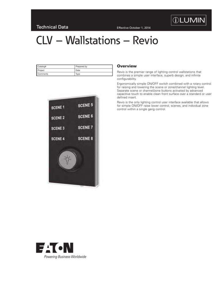
Revio is the premier range of lighting control wallstations that
combines a simple user interface, superb design, and infinite
configurability.
Ergonomically simple ON/OFF switch combined with a rotary control
for raising and lowering the scene or zone/channel lighting level.
Separate scene or channel/zone buttons activated by advanced
capacitive touch to enable clean front surface over a standard or user
defined insert.
Revio is the only lighting control user interface available that allows
for simple ON/OFF raise lower control, scenes, and individual zone
control within a single gang control.
Technical Data
CLV – Wallstations – Revio
October 2014
Specifications
Electrical
Mechanical
Environmental Data
Dimensions
12 Vdc supply voltage via the network
iCANnet connection: Screw terminals with
two part connectors, able to accept 16 AWG
(1.5mm²) stranded or solid wire.
8 touch sensitive switches individually
illuminated with the selected scene brightly
lit
Audible feedback when a switch is activated
Rotary control provides raise/lower function
Illuminated On/Off switch situated in the
middle of the rotary control. A double tap of
the On/Off switch overrides the fade time
Flash memory for future proof upgradeability
Variable fade times programmable from 0.1
seconds to 60 minutes per button
Built-in infrared receiver with learnable
remote codes
Tested to withstand 12kV electro-static
discharge without damage or memory loss
Network Communication using iCANnet
(CANbus)
Covered by liquid glass style polycarbonate
cover ensuring UV protection, longevity
of color/graphics, and an easily cleanable
surface
“Clean” switch, when pressed, allows
the wall station to be wiped clean without
changing light levels
Suitable for standard single gang NEMA wall
boxes only, not to be used with multi-gang
wall boxes
All plastic construction with a separate steel
chassis that is affixed to wall box as first fix
with the unit attaching to chassis with screws
Temperature Range: 32°F to 104°F (0°C 40°C)
Humidity: 0% - 95% non-condensing
(Inches/mm)
From 1 to 8 configurable buttons per control
Mounts to standard NEMA style Backbox, single gang only
• From 1 to 8 configurable buttons per control
• Mounts to standard NEMA style Backbox, singl
Standards
Button Functionality
Using iCANsoft each button can be configured to perform the
following functions:
Scene Selection
Scene Raise/Lower
Zone/Channel Raise/Lower
• From 1 to 8 configurable buttons per control
• Mounts to standard NEMA style Backbox, single gang only
Toggle ON/OFF
Open/Close (for curtains, blinds, and partitions)
Raise/Lower (motorized screens/blinds)
Sequence control (16 sequences with up to 128 steps)
Two methods of configuration
A range of six standard wall station templates can be selected via
the Source Controller for easy configuration.
Using iCANsoft where each button can be configured to perform a
variety of functions
• From 1 to 8 configurable buttons per control
• Mounts to standard NEMA style Backbox, single gang only
2
www.coopercontrol.com
Technical Data
CLV – Wallstations – Revio
October 2014
Wiring Diagram
Supplied Parts
Rear Chassis Plate
Main Body
Inner Sheet
Front Cover
Each Source Controller can power up to 10 wallstations/devices.
These devices must be within 1000ft of the Source Controller.
For devices further from a Source Controller add a 15 Vdc power supply.
100 devices/addresses per physical segment on iCANnet (BN-2-NA can be added
to combine more than 100 devices together, up to 65000 total)
REMOTE PC
LOCAL PC
SC277-24-UN-3P-ML-20
SC277-12-UN-3P-ML-20
DRY CONTACT
CLOSURE
TUNGSTEN
DMX OUTPUT CONSOLE BY
ZERO 88 OR OTHERS
INTERNET
iCANnet cable type – Cooper LCCNP (Non Plenum) Cable
Belden 1502R (Non Plenum) or 1502P (Plenum).ROUTER
orLAPTOP
LCCP
DMX512
DISCHARGE
(Plenum) or
2, 3 & 4 WIRE
FLUORESCENT
OCCUPANCY
SECURITY
AV
Wallstations
require
power from a Source
Controller or a 15 Vdc External
SENSOR
SYSTEM
COMPONENTS
Power Supply. Each Source Controller
can power up to 10 wallstations/devices
over a 1000 foot distance. For more than 10 wallstations/devices
per Source
WiFi
Controller add a 15 Vdc External Power Supply. For wallstations/devices
further than 1000 feet from a Source Controller add a 15 Vdc External
Power Supply.
ETHERNET
COLD CATHODE
COLOR CHANGING
FIXTURES
100 Devices per physical segment on iCANnet, maximum segment distance of
CLS-4TSB-RL-W-IR
1000m/3200ft. A BN-2-NA can be added to combine more than 100 devices
SI-2-NA
together (up to 65,000 total) and to extend network cable
distance.
UIG-2-NA
RS232
CONTACT
CLOSURE
INPUT
DRY CONTACT
CLOSURE
CLS-3TLB-W-IR
CLS-1TLB-W-IR
Scene 1
Scene 1
Scene 2
Scene 1
Scene 3
Scene 2
Scene 4
Scene 3
HH17IR
iCANnet
Sample System Topology
Cable type - Cooper LCCNP (NON PLENUM) OR Cooper LCCP (PLENUM) Cable or Belden™ 1502R (NON PLENUM) or 1502P (PLENUM)
Maximum segement distance of 1000m/3200ft per segment
SC120-12-UN-1P-ML-20
CRESTRON
TUNGSTEN
AMX
DISCHARGE
Each Source Controller can power up to 10 wallstations/devices.
These devices must be within 1000ft of the Source Controller.
For devices further from a Source Controller add a 15 Vdc power supply.
100 devices/addresses per physical segment on iCANnet (BN-2-NA can be added
to combine more than 100 devices together, up to 65000 total)
RS485
2, 3 & 4 WIRE
FLUORESCENT
Contact
closure
input
COLD CATHODE
SC120-06-UN-1P-ML-20
TUNGSTEN
DISCHARGE
COLOR CHANGING
FIXTURES
2, 3 & 4 WIRE
FLUORESCENT
COLD CATHODE
CLV-44-RL-W-IR
CLV-40-RL-W-IR
CLV-44Z-RL-W-IR
COLOR CHANGING
FIXTURES
TSC-30-SS-NA
9Vdc
SUPPLY
HH17IR
iCANnet
Cable type - Cooper LCCNP (NON PLENUM) OR Cooper LCCP (PLENUM) Cable or Belden™ 1502R (NON PLENUM) or 1502P (PLENUM)
Maximum segement distance of 1000m/3200ft per segment
www.coopercontrol.com
3
Technical Data
CLV – Wallstations – Revio
October 2014
Printed Inserts
Show below are the range of standard color options
Color
White
Black
Gray
Ivory
Code
W
B
G
V
Standard Button Configurations
1
2
4
Horizontal
4
Vertical
6
8
4 Scenes (left)
4 Zones (right)
CLV-10-RL-IR
CLV-11-RL-IR
CLV-22-RL-IR
CLV-40-RL-IR
CLV-33-RL-IR
CLV-44-RL-IR
CLV-44Z-RL-IR
Buttons
Ordering
CLV - 4 - 4Z - RL - W - IR - T1
Cooper
iLumin
Ineo
Standard Text Offerings can be selected by
adding one of the below to the model number
Blank T1 T2 T3 Number of Buttons in 1st Column
1-4
Standard Text is Scene 1,
Scene 2, etc.
Scene 1, Scene 2, etc.
Preset 1, Preset 2, etc.
General, Meeting, Seminar, Lecture
Lunch, Cocktails, Dinner, Special
IR Receiver
IR
Number of Buttons in 2nd Column
0-4 = Standard Text is Scene 1, Scene 2, etc.
4Z = Standard Zone 1-4
Raise/Lower Function
RL = Always Fitted
= Fitted
Color
W
B
V
G
=
=
=
=
White
Black
Ivory
Gray
Eaton
1000 Eaton Boulevard
Cleveland, OH 44122
United States
Eaton.com
Eaton’s Cooper Controls Business
203 Cooper Circle
Peachtree City, GA 30269
coopercontrol.com
© 2014 Eaton
All Rights Reserved
Printed in USA
Publication No. ACC140928
October 1, 2014
Eaton is a registered trademark.
All other trademarks are property
of their respective owners.


