Technical Data
Effective October 1, 2014
BN-2-NA – Network Bridge
Catalog#
Prepared by
Project
Date
Comments
Type
Overview
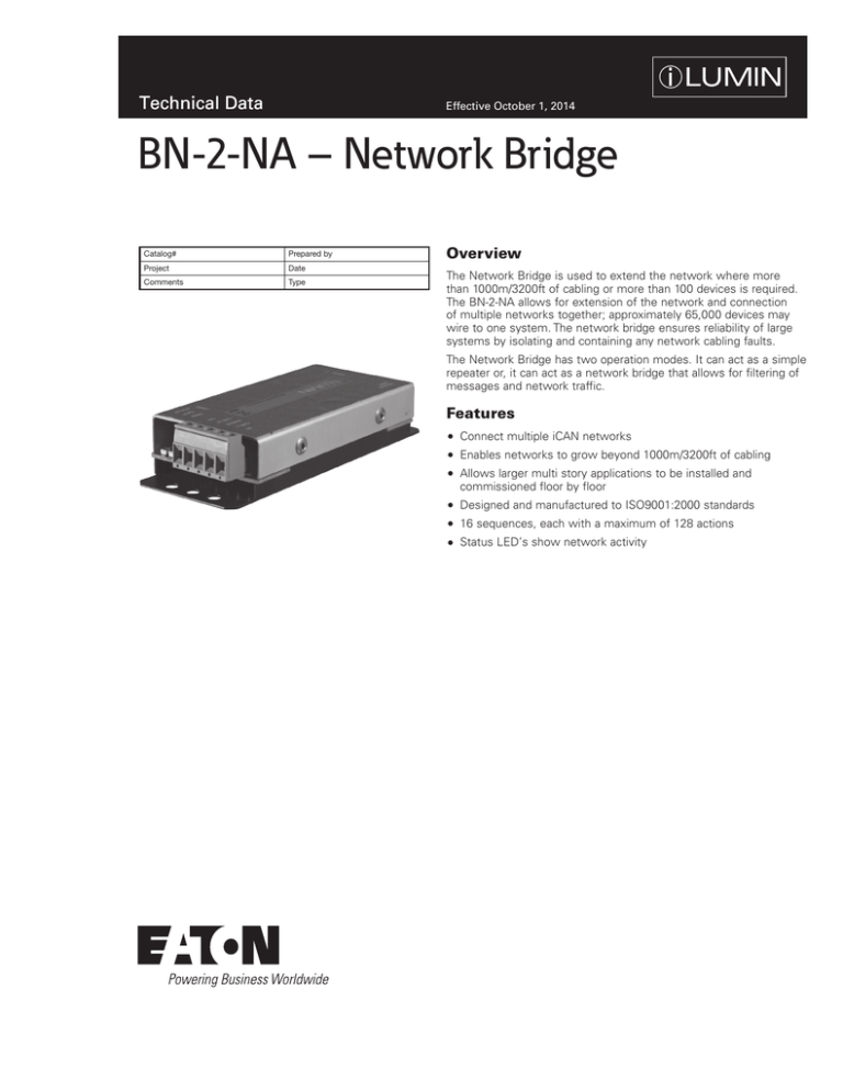
The Network Bridge is used to extend the network where more
than 1000m/3200ft of cabling or more than 100 devices is required.
The BN-2-NA allows for extension of the network and connection
of multiple networks together; approximately 65,000 devices may
wire to one system. The network bridge ensures reliability of large
systems by isolating and containing any network cabling faults.
The Network Bridge has two operation modes. It can act as a simple
repeater or, it can act as a network bridge that allows for filtering of
messages and network traffic.
Features
Connect multiple iCAN networks
Enables networks to grow beyond 1000m/3200ft of cabling
Allows larger multi story applications to be installed and
commissioned floor by floor
Designed and manufactured to ISO9001:2000 standards
16 sequences, each with a maximum of 128 actions
Status LED’s show network activity
Technical Data
BN-2-NA – Network Bridge
October 2014
Specifications
Electrical Data
Mechanical Data
Environmental Data
Requirements
Dimensions
Supply: 12 Vdc via the network
iCANnet connection: Screw terminals with
two part connectors, able to accept 16 AWG
(1.5mm2) stranded or solid wire
2-part aluminium housing.
Mounting: 6 holes for screw mounting or
Ty-wraps
Suitable for Eaton’s Cooper LC cable
Temperature Range:
32°F to 104°F (0°C - 40°C)
Humidity: 0% - 95% non-condensing
The BN-2-NA optically isolates the connected
network segments and does not pass power
through to the connected network segment.
Adequate power must be on both sides of
the BN-2-NA to power the devices along the
connected segments. It may be necessary
to add EXPS-15V power supplies to boost
available power when BN-2-NA devices are
added. One source controller or EXPS-15V
power supply is capable of powering 10
devices over a 1000 foot cable run. Ensure
power is adequate on both connected
network segments. When used in bridge
mode, ensure that the main bridge backbone
has adequate EXPS-15V supplies to power
the backbone network.
(Inches/mm)
Standards
Wiring Diagram
2
www.coopercontrol.com
Technical Data
BN-2-NA – Network Bridge
October 2014
Sample System Topology
In Repeater mode, the BN-2-NA allows extension of the network an additional 3200 feet and 100 devices per repeater.
All messages are passed through all network segments without filtering.
In Bridge mode, the BN-2-NA connects a main bridge backbone to up to 250 network segments. Message filtering
will occur to allow for maximum network usage.
SC277-24-UN-3P-ML-20
SC277-12-UN-3P-ML-20
DMX512
SC120-06-UN-1P-ML-20
To additional
Bridged
Networks
BN-2-NA
Repeater
Mode
BN-2-NA
Repeater
Mode
CLV-40-RL-G-IR
UIG-2-NA
SI-2-NA
CONTACT
CLOSURE
INPUT
DRY CONTACT
CLOSURE
CLS-4STB-RL-W-IR
TSC-30-SS-NA
CLS-1TLB-W
Scene 1
Scene 1
Scene 2
Scene 3
Scene 4
HH17IR
BN-2-NA
Bridge
Mode
iCANnet
9Vdc
SUPPLY
Cable type - Cooper LCCNP (NON PLENUM) OR Cooper LCCP (PLENUM) Cable or Belden™ 1502R (NON PLENUM) or 1502P (PLENUM)
Maximum segement distance of 1000m/3200ft per segment
SC277-12-UN-3P-ML-20
DRY CONTACT
CLOSURE
SC120-06-UN-1P-ML-20
SC120-06-UN-1P-ML-20
SECURITY OCCUPANCY
SENSOR
SYSTEM
AV
COMPONENTS
BN-2-NA
Repeater
Mode
BN-2-NA
Repeater
Mode
CLS-1TLB-W
CLV-44-RL-G-IR
Scene 1
HH17IR
BN-2-NA
Bridge
Mode
UIG-2-NA
RS232
iCANnet
Cable type - Cooper LCCNP (NON PLENUM) OR Cooper LCCP (PLENUM) Cable or Belden™ 1502R (NON PLENUM) or 1502P (PLENUM)
Maximum segement distance of 1000m/3200ft per segment
Ordering
Model
Description
BN-2-NA
Network Bridge
Eaton
1000 Eaton Boulevard
Cleveland, OH 44122
United States
Eaton.com
Eaton’s Cooper Controls Business
203 Cooper Circle
Peachtree City, GA 30269
coopercontrol.com
© 2014 Eaton
All Rights Reserved
Printed in USA
Publication No. ACC140935
October 1, 2014
Eaton is a registered trademark.
All other trademarks are property
of their respective owners.
SI-2-NA


