Impedances (Solutions) HSSP Audio and Speaker-building March 10, 2007
advertisement
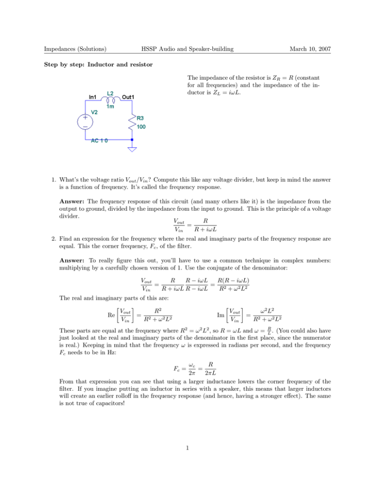
Impedances (Solutions) HSSP Audio and Speaker-building March 10, 2007 Step by step: Inductor and resistor The impedance of the resistor is ZR = R (constant for all frequencies) and the impedance of the in­ ductor is ZL = iωL. 1. What’s the voltage ratio Vout /Vin ? Compute this like any voltage divider, but keep in mind the answer is a function of frequency. It’s called the frequency response. Answer: The frequency response of this circuit (and many others like it) is the impedance from the output to ground, divided by the impedance from the input to ground. This is the principle of a voltage divider. R Vout = R + iωL Vin 2. Find an expression for the frequency where the real and imaginary parts of the frequency response are equal. This the corner frequency, Fc , of the filter. Answer: To really figure this out, you’ll have to use a common technique in complex numbers: multiplying by a carefully chosen version of 1. Use the conjugate of the denominator: R R − iωL R(R − iωL) Vout = = 2 R + iωL R − iωL R + ω 2 L2 Vin The real and imaginary parts of this are: � � R2 Vout Re = 2 R + ω 2 L2 Vin � Im � Vout ω 2 L2 = 2 Vin R + ω 2 L2 These parts are equal at the frequency where R2 = ω 2 L2 , so R = ωL and ω = R L . (You could also have just looked at the real and imaginary parts of the denominator in the first place, since the numerator is real.) Keeping in mind that the frequency ω is expressed in radians per second, and the frequency Fc needs to be in Hz: R ωc = 2π 2πL From that expression you can see that using a larger inductance lowers the corner frequency of the filter. If you imagine putting an inductor in series with a speaker, this means that larger inductors will create an earlier rolloff in the frequency response (and hence, having a stronger effect). The same is not true of capacitors! Fc = 1 Impedances (Solutions) HSSP Audio and Speaker-building 3. What kind of filter is this? Lowpass, highpass, bandpass, notch, or something else? March 10, 2007 Answer: This is a lowpass filter. It removes high frequencies and allows low frequencies to pass on to the load (speaker) un-altered. 4. Compute the corner frequency of the filter, in Hz, using the component values on the schematic. Answer: Using the expression for Fc above: R 100 = = 1.6 × 10⁴ Hz = 16 kHz 2π × 10−3 2πL That’s actually a pretty high frequency; it would be difficult to hear the effect of this filter on music. Note, however, that 100 ohms is a lot higher than the impedance of a typical speaker (4 to 8 ohms). If you put a 1 mH inductor in series with a speaker, the corner frequency will be closer to 1 kHz, and you’ll definitely be able to hear that. Fc = Still step by step: Notch filter This circuit is a little more complicated. Let’s try to figure out what it does without making a mess of complex numbers. 1. If the L-C combination has a really big impedance, what’s the ratio Vout /Vin ? Answer: This is a voltage divider too! If the impedance from the output to ground is really big, than it makes up almost all of the impedance from the input to ground. Vout =1 Vin 2 Impedances (Solutions) HSSP Audio and Speaker-building 2. At what frequency does the L-C combination have zero impedance? (Hint: 1 i March 10, 2007 1 i = −i, so iωC = − ωC .) Answer: Look at the impedance of an inductor and capacitor in series, set it to 0, and solve for ω: 1 i = iωL − =0 ωC iωC 1 ωL = ωC ω 2 LC = 1 1 1 √ ω=√ →F = 2π LC LC 3. If the L-C combination has zero impedance, what’s the ratio Vout /Vin ? ZL + ZC = iωL + Answer: If you know the L-C combination has zero impedance, that means you can act like it’s a wire. So we’re left with a simple resistive voltage divider. There’s a resistor (R2 ) from the output to ground, and two series resistors (R1 and R2 ) from input to ground: R2 Vout = R1 + R2 Vin 4. What kind of filter is this? Lowpass, highpass, bandpass, notch, or something else? Answer: This filter doesn’t do much (since Vout /Vin = 1) at most frequencies. But it does block out signals to some extent (Vout /Vin = R1R+2R2 ) at a particular frequency. That’s called a notch filter. 5. Compute the numerical value of your first three answers (output ratios and frequency). Answer: All we have to do is plug numbers into the above formulas: • Filter gain at most frequencies: VVout =1 in 1 √ • Resonance frequency: F = 2π LC = √ 1 = 1×10⁻⁹ R2 4 R1 +R2 = 14 2π • Filter gain at notch frequency: Vout Vin = 5030 Hz = 2 7 6. Try to draw the frequency response graph of this circuit. Answer: You can see that the frequency response is flat over most of the audio range, with a dip of about -11 dB (close to 27 ) at 5 KHz, just as we predicted. (Ask me if you’re curious how to simulate circuits this way!) 3 MIT OpenCourseWare http://ocw.mit.edu Audio and Speaker Electronics Spring 2007 For information about citing these materials or our Terms of Use, visit: http://ocw.mit.edu/terms.

