EE 461G Mid-Term Exam
advertisement
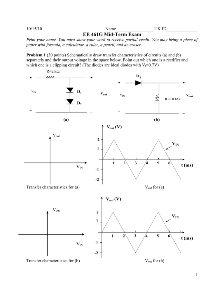
10/15/10 Name_________________ UK ID______________ EE 461G Mid-Term Exam Print your name. You must show your work to receive partial credit. You may bring a piece of paper with formula, a calculator, a ruler, a pencil, and an eraser. Problem 1 (30 points) Schematically draw transfer characteristics of circuits (a) and (b) separately and their output voltage in the space below. Point out which one is a rectifier and which one is a clipping circuit? (The diodes are ideal diodes with Vf=0.7V) R=2 k + D1 + + vIN D1 vout + vIN vout R=10 k D2 – – – – (a) (b) Vout (V) Vout 2 VIN 1 1 VIN 2 3 4 5 6 t (ms) -1 -2 Transfer characteristics for (a) Vout for (a) Vout (V) Vout 2 VIN 1 1 VIN 2 3 4 5 6 t (ms) -1 -2 Transfer characteristics for (b) Vout for (b) 1 Problem 2 (35 points) Considering the following circuits: (a) Derive the equations for transfer characteristics using the piecewise linear model (both diodes are the same with rd=0.5 k and Vf=0.7V); (b) Draw the transfer characteristics; (c) Draw the output voltage curves Vout in the graph below. 1 k + vin V2=3V D1 ~ vout D2 V1=3V – Vout (V) 10 VIN 5 0 1 2 3 4 5 6 7 8 9 10 11 t (ms) -5 -10 2 Problem 3 (35 points) A bridge power supply circuit is shown below. Assuming the turn-on voltage of all diodes is Vf=0.7V. The input is vin= 10Sin(2ft) where f=1kHz. In the circuit, C=20F and R1=0.2k. For the Zener diode (Z1), Vf=0.7V and Vzk=5V. (a) Calculate the ripple voltage on the capacitor for Vin at the peak. (b) Draw the curves of vc vs. t and vout vs. t together with the curve of vin vs. t (c) If the load current (IL) varying from 5 mA to 10 mA, what are the maximum and minimum powers on the Zener diode (Z1)? + D4 D1 R1 I1 vin IL + vout I2 D3 – D2 vc C Z1 Load – 3

