Unified Engineering I Fall 2003
advertisement
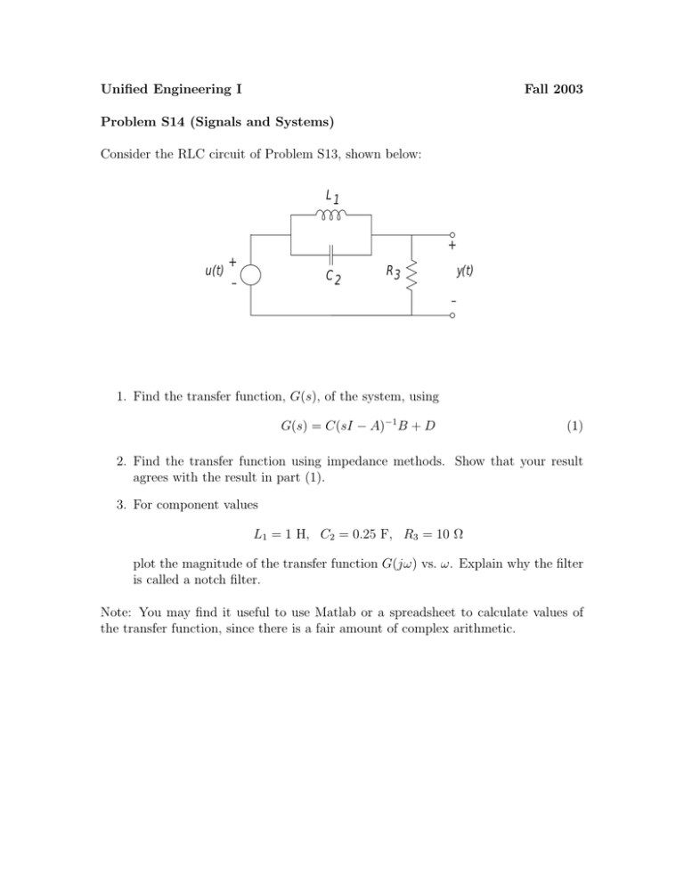
Unified Engineering I Fall 2003 Problem S14 (Signals and Systems) Consider the RLC circuit of Problem S13, shown below: L1 + u(t) + C2 – R3 y(t) – 1. Find the transfer function, G(s), of the system, using G(s) = C(sI − A)−1 B + D (1) 2. Find the transfer function using impedance methods. Show that your result agrees with the result in part (1). 3. For component values L1 = 1 H, C2 = 0.25 F, R3 = 10 Ω plot the magnitude of the transfer function G(jω) vs. ω. Explain why the filter is called a notch filter. Note: You may find it useful to use Matlab or a spreadsheet to calculate values of the transfer function, since there is a fair amount of complex arithmetic.
