OEM Equipment
Catalog Data
CA800019EN
Effective July 2015
Supersedes 800-65 August 2012
COOPER POWER
SERIES
Two-position sidewall (horizontal) and
cover (vertical) mounted loadbreak
switches
General
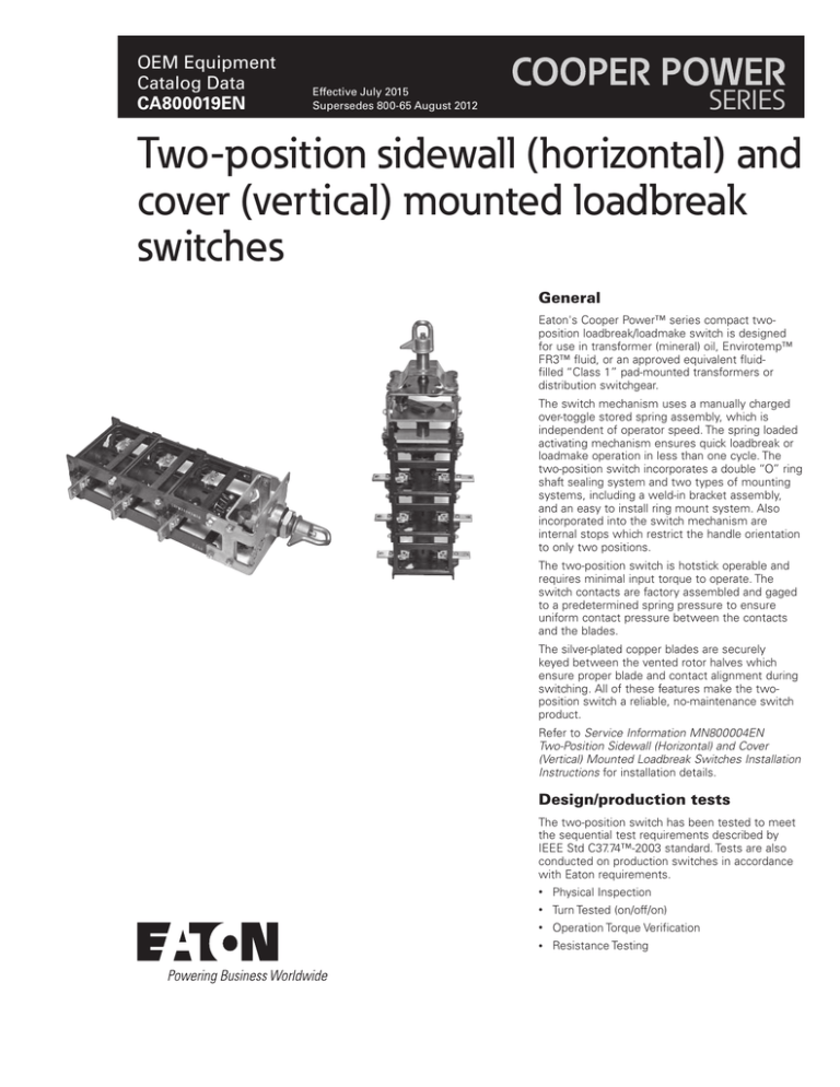
Eaton's Cooper Power™ series compact twoposition loadbreak/loadmake switch is designed
for use in transformer (mineral) oil, Envirotemp™
FR3™ fluid, or an approved equivalent fluidfilled “Class 1” pad-mounted transformers or
distribution switchgear.
The switch mechanism uses a manually charged
over-toggle stored spring assembly, which is
independent of operator speed. The spring loaded
activating mechanism ensures quick loadbreak or
loadmake operation in less than one cycle. The
two-position switch incorporates a double “O” ring
shaft sealing system and two types of mounting
systems, including a weld-in bracket assembly,
and an easy to install ring mount system. Also
incorporated into the switch mechanism are
internal stops which restrict the handle orientation
to only two positions.
The two-position switch is hotstick operable and
requires minimal input torque to operate. The
switch contacts are factory assembled and gaged
to a predetermined spring pressure to ensure
uniform contact pressure between the contacts
and the blades.
The silver-plated copper blades are securely
keyed between the vented rotor halves which
ensure proper blade and contact alignment during
switching. All of these features make the twoposition switch a reliable, no-maintenance switch
product.
Refer to Service Information MN800004EN
Two-Position Sidewall (Horizontal) and Cover
(Vertical) Mounted Loadbreak Switches Installation
Instructions for installation details.
Design/production tests
The two-position switch has been tested to meet
the sequential test requirements described by
IEEE Std C37.74™-2003 standard. Tests are also
conducted on production switches in accordance
with Eaton requirements.
•
Physical Inspection
•
Turn Tested (on/off/on)
•
Operation Torque Verification
•
Resistance Testing
Catalog Data CA800019EN
Two-position sidewall (horizontal) and cover (vertical)
mounted loadbreak switches
Effective July 2015
Table 1. Ratings and Characteristics
Description
Units
Ratings
Maximum rating phase-to-phase
Maximum rating phase-to-ground
Power Frequency
Current Rating (Continuous)
Switching Current
Magnetizing Interrupting Current
Cable Charging Current
kV
kV
Hz
A
A
A
A
15.5
8.9
60
550
550
21
10
27.6
15.6
60
400
400
21
25
38
21.9
60
300
300
10.5
20
46
26.5
60
65
65
10.5
15
10 cycle symmetric rms
10 cycle asymmetric rms
45 cycles symmetric rms
1 second symmetric rms
2 second symmetric rms
3 second symmetric rms
kA
kA
kA
kA
kA
kA
12
19.2
16
12
8
7
12
19.2
16
12
8
7
12
19.2
16
12
8
7
12
19.2
16
12
8
7
10 cycle symmetric rms
10 cycle asymmetric rms
15 cycle symmetric rms
15 cycle asymmetric rms
kA
kA
kA
kA
12
19.2
12
19.2
12
19.2
12
19.2
To ground and between phases
Across open contacts
kV
kV
200
235
200
235
200
235
200
235
To ground and between phases
Across open contacts
kV
kV
70
95
70
95
70
95
70
95
To ground, between phases and across
kV
103
103
103
103
kV
2,000
26
2,000
26
2,000
26
2,000
26
2,000
Rated Voltage
Fault Withstand Current (Momentary)
Fault Close and Latch
Impulse Withstand Voltage (1.2/50 µs)
Power Frequency Withstand (1 minute)
DC Withstand (15 minutes)
Contacts
Corona (Extinction)
Mechanical Life (Minimum Operations)
Ø 2.00" (51 mm) EXTERIOR MOUNTING SURFACE
MUST BE FLAT WITHIN .010" OVER ENTIRE AREA.
2.00"
(50.8 mm)
2.38"
(60.3 mm)
Ø 1.32" +.030 HOLE
-.000
(33.5 mm +0.8
-0.0)
.40"
(10.2 mm)
.63"
(15.9 mm)
.662"
(16.8 mm)
1.50"
(38.1 mm)
Figure 2. Padlockable handle.
R .140"
(3.56 mm)
Ø 4.00" (102 mm) INTERIOR MOUNTING SURFACE
MUST BE CLEAR OF OBSTRUCTIONS.
Figure 1. Hole placement (Ring Mount system).
2
www.eaton.com/cooperpowerseries
1.75"
(44.5 mm)
Catalog Data CA800019EN
Two-position sidewall (horizontal) and cover (vertical) mounted loadbreak switches
2.82"
(72 mm)
4.88"
(124 mm)
Effective July 2015
"A"
3.8"
(97 mm)
"B"
.80"
(20 mm)
1.4"
(35 mm)
3.8"
(97 mm)
SEE NOTE 4
8.29"
(210 mm)
5.27"
(134 mm)
8.3"
(210 mm)
.07"
(2 mm)
1.19"
(30 mm)
TANK WALL
Ø.393"
(10 mm)
WELD-IN MOUNTING BRACKET
Hole diameter in tank wall for Weld-in mounting
bracket must be 1.00" ± 0.10 (25.4 mm).
Figure 3. Line illustration with dimensions of loadbreak switch with “WELD-IN SYSTEM” for horizontal or vertical mounting.
(Shown with "Full" deck extension.)
Notes:
1. Dimensions given are for reference only.
2. Switch shown with contacts “CLOSED” and flat of shaft on “BOTTOM” to position cast handle pointer to 9 o’clock when looking at switch with side marked “TOP” up.
Handle is rotated approximately 90° CCW when it is in the “OPEN” position.
Table 2. Dimensional Information for Figure 3
Number of
Decks or
Phases
Dimensions w/Standard
Configuration
(No Extensions)
Inches/(mm)
Dimensions w/Short
(1/2) Deck Extension
Inches/(mm)
"A"
“A”
1
8.14 (207)
2
11.95 (303)
3
15.75 (400)
"B"
“B”
10.2 (259)
6.75 (171)
14.0 (356)
17.8 (452)
Dimensions w/Full
Deck Extension
Inches/(mm)
Dimensions w/Short
(1/2) Deck + Full Deck
Extension Inches/(mm)
“A”
"A"
“B”
12.0 (305)
8.8 (224)
15.8 (400)
19.6 (497)
"B"
14.0 (356)
10.6 (269)
17.8 (452)
12.6 (321)
21.6 (549)
www.eaton.com/cooperpowerseries
3
Catalog Data CA800019EN
Two-position sidewall (horizontal) and cover (vertical)
mounted loadbreak switches
Effective July 2015
Table 3. Dimensional Information for Figure 4
Ring Mount w/Standard Configuration (No Extensions)
Inches/(mm)
Ring Mount w/Full Deck Extension
Inches/(mm)
Number of Decks or
Phases
"A"
Number of Decks or
Phases
"A"
1
7.83 (198 mm)
1
11.6 (295 mm)
2
11.64 (296 mm)
2
15.4 (391 mm)
3
15.44 (392 mm)
3
19.3 (490 mm)
"B"
6.4
(163 mm)
Ring Mount w/ 1/2 Deck Extension
Inches/(mm)
Number of Decks or
Phases
1
9.9 (251 mm)
13.7 (34.7 mm)
3
17.5 (444 mm)
"B"
Number of Decks or
Phases
1
13.7 347 mm)
8.5
(215 mm)
2
17.5 (444 mm)
3
21.3 (541 mm)
4.88
[124.0]
Ø.393
[9.98]
(259 mm)
[81]
MTG
HOLES
TYP.
B
.75
SEE
NOTE 8
"A"
"B"
12.3
(312 mm)
A
3.2
Ø.44
[11.1]
10.2
Ring Mount with 1/2 Deck + Full Deck Extension
Inches/(mm)
"A"
2
"B"
3.8
3.8
[97]
[97]
[19.1]
5.27
[133.8]
HANDLE & NUT
FURNISHED
WITH SWITCH
1.88
[47.8]
1.00
[25.3]
TWO (2) MYLAR WASHERS
INDICATOR PLATE IS
OPTIONAL,SEE NOTE 5
1.4
[35]
Figure 4. Line illustration with dimensions of loadbreak switch with "Ring Mount system" for horizontal or vertical mounting.
Notes:
1. Dimensions given are for reference only.
2. Switch shown with contacts “CLOSED” and flat of shaft on “BOTTOM” to position cast handle pointer to 9 o’clock when looking at switch with side marked “TOP” up.
Handle is rotated approximately 90° CCW when it is in the “OPEN” position.
3. Ring mount switch can be mounted turned 90° sideways utilizing second slot in mounting insert.
4
www.eaton.com/cooperpowerseries
Catalog Data CA800019EN
Two-position sidewall (horizontal) and cover (vertical) mounted loadbreak switches
Effective July 2015
Ordering information—horizontal mount
To order the two-position sidewall (horizontal) mounted loadbreak
switch, specify catalog numbers as listed in Table 4.
Table 4. Loadbreak Switch Significant Digit Catalog Numbers
1
2
3
L S 2
4
R
5
6
7
3
3
8 H 3 N
CODE
POWER RATING
CODE
PRODUCT
L
LOADBREAK
338
S
SWITCH
427
2
2-POSITION
515
550 A, 15 kV
646***
65 A, 46 kV
CODE
INSTALLATION
R
RING MOUNT SYSTEM
W
WELD-IN MOUNT
8
9
CODE
10
11
12
1
A
STYLE**
300 A, 38 kV
N
NORMAL
400 A, 27 kV
S
STAINLESS STEEL/
NON-CORROSIVE
Note: Digit 10 must be "S" if digit 4 is "W".
CODE
INDICATOR PLATE*
CODE
ORIENTATION
1
NO INDICATOR PLATE
H
HORIZONTAL
2
F
FULL - FULL DECK
EXTENSION
WITH OPTIONAL
INDICATOR PLATE
CODE
NUMBER OF PHASES
1
ONE
2
TWO
3
THREE
(Indicator plate not available for
Weld-In system)
CODE
HARDWARE KITS
A
HARDWARE KIT
B
HARDWARE KIT FOR
STAINLESS STEEL/NONCORROSIVE SWITCHES
C
NO HARDWARE KIT
Note: Digit 12 should always be "B" or "C" if digit 10 is "S".
* NORMAL style switch has all externally located parts built from plated steel, aluminum and brass materials.
** STAINLESS STEEL/NON-CORROSIVE style switch has all externally located parts built from stainless steel and brass materials.
STAINLESS STEEL/NON-CORROSIVE style ring mount switch should always be matched with a hardware kit having a brass handle and a
stainless steel nut.
***If digits 5-7 are "646" then digit 8 must be "F".
Notes: Catalog Number Example shown in Table 5 represents a standard, Bolt-In system, 300 A, 38 kV, Horizontal, three-phase, standard
plated steel external parts, w/o indicator plate, with brass handle hardware kit, 6:00/9:00 positions. (Other handle position options available upon request for 9:00/12:00, 12:00/3:00, and 3:00/6:00 positions. Consult your Eaton representative for details.)
CLOSE
2.75"
(70 mm)
2.75"
(70 mm)
OPEN
Figure 5. Index plate (optional).
NNote: For different orientations see drawing 4201192N.
www.eaton.com/cooperpowerseries
5
Catalog Data CA800019EN
Two-position sidewall (horizontal) and cover (vertical)
mounted loadbreak switches
Effective July 2015
Ordering information—vertical mount
To order the two-position cover mount (vertical) mounted loadbreak
switch, specify catalog numbers as listed in Table 5.
Table 5. Loadbreak Switch Significant Digit Catalog Numbers
1
2
3
L S 2
4
W
5
6
7
3
3
8 F 3
CODE
PRODUCT
CODE
L
LOADBREAK
338
300 A, 38 kV
S
SWITCH
427
400 A, 27 kV
2
2-POSITION
646*
65 A, 46 kV
8
POWER RATING
9
10
S
CODE
S
INSTALLATION
W
WELD-IN MOUNT
R
RING MOUNT
CODE
NUMBER OF PHASES
1
ONE
2
TWO
3
THREE
VERTICAL ORIENTATION
S
SHORT - 1/2 DECK EXTENSION
F
FULL - FULL DECK EXTENSION
L
LONG - 1/2 + FULL DECK
EXTENSION
1
B
STAINLESS STEEL/
NON-CORROSIVE
INDICATOR PLATE
1
NO INDICATOR PLATE
2
WITH OPTIONAL
INDICATOR PLATE
(Indicator plate not
available for weld-in
system)
CODE
CODE
12
STYLE
CODE
CODE
11
HARDWARE KITS
B
HARDWARE KIT W/BRASS
HANDLE
C
NO HARDWARE KIT
* If digits 5-7 are "646", digit 8 must be "F" or "L" for LS2W version (vertical mount)
Notes: Catalog Number Example shown in Table 6 represents a standard, Weld-In system, 300 A, 38 kV, Vertical, 3-phase, standard plated
steel external parts, w/o indicator plate, with brass handle hardware kit, 6:00/9:00 positions. (Other handle position options available
upon request for 9:00/12:00, 12:00/3:00, and 3:00/6:00 positions. Consult your Eaton representative for details.)
Table 6. Accessory Parts
6
Description
Catalog Number
Weld-In Bracket
2238061C01M
–
Standard (Brass) Handle
2200726B05
4201184N
Padlockable (Brass) Handle
2239000B15
4201093N
Indicator Plate (6:00/9:00)
2238709C01
4201192N
www.eaton.com/cooperpowerseries
Drawing
Two-position sidewall (horizontal) and cover (vertical) mounted loadbreak switches
Catalog Data CA800019EN
Effective July 2015
This page intentionally left blank.
www.eaton.com/cooperpowerseries
7
Catalog Data CA800019EN
Two-position sidewall (horizontal) and cover (vertical)
mounted loadbreak switches
Effective July 2015
Eaton
1000 Eaton Boulevard
Cleveland, OH 44122
United States
Eaton.com
Eaton’s Cooper Power Systems Division
2300 Badger Drive
Waukesha, WI 53188
United States
Eaton.com/cooperpowerseries
© 2015 Eaton
All Rights Reserved
Printed in USA
Publication No. CA800019EN
Eaton and Cooper Power are valuable
trademarks of Eaton in the U.S. and other
countries. You are not permitted to use these
trademarks without the prior written consent
of Eaton.
IEEE Std C37.74™-2003 standard is a
trademark of the Institute of Electrical and
Electronics Engineers, Inc., (IEEE). This
publication is not endorsed or approved by
the IEEE.
Envirotemp™ and FR3™ are licensed
trademarks of Cargill, Incorporated.
For Eaton's Cooper Power series loadbreak
switches product information call 1-877-277-4636
or visit: www.eaton.com/cooperpowerseries.


