Loadbreak
Connector
CA650099EN
COOPER POWER
SERIES
Effective December 2015
Supersedes 500-28-7C November 2011
200 A 25 kV and 28 kV class loadbreak
elbow connector with optional integral
jacket seal-Canadian Edition
General
Eaton’s Cooper Power™ series loadbreak elbow
connector is a fully-shielded and insulated
plug-in termination for connecting underground
cable to transformers, switching cabinets and
junctions equipped with loadbreak bushings. The
elbow connector and bushing insert comprise
the essential components of all loadbreak
connections. The elbow connector is a fully rated
200 A switching device, designed in accordance to
IEEE Std 386™-2006 standard.
Loadbreak elbows are molded using high
quality peroxide-cured insulating and semiconducting EPDM rubber. Standard features
include a coppertop connector, tin-plated copper
loadbreak probe with an ablative arc-follower tip
and stainless steel reinforced pulling-eye. An
optional capacitive test point, made of corrosion
resistant plastic, is available for use with fault
indicators (see Catalog Data CA320002EN and
CA320003EN).
Cable ranges are designed to accept a wide
range of cable conductor and insulation sizes
with just three elbows and accommodate cable
manufactured to either AEIC or ICEA standards.
The coppertop compression connector is a
standard item to transition from the cable to
the loadbreak probe. An aluminum crimp barrel
is inertia-welded to a copper lug. The aluminum
barrel makes the connector easy to crimp and the
copper lug ensures a reliable, tight, cool operating
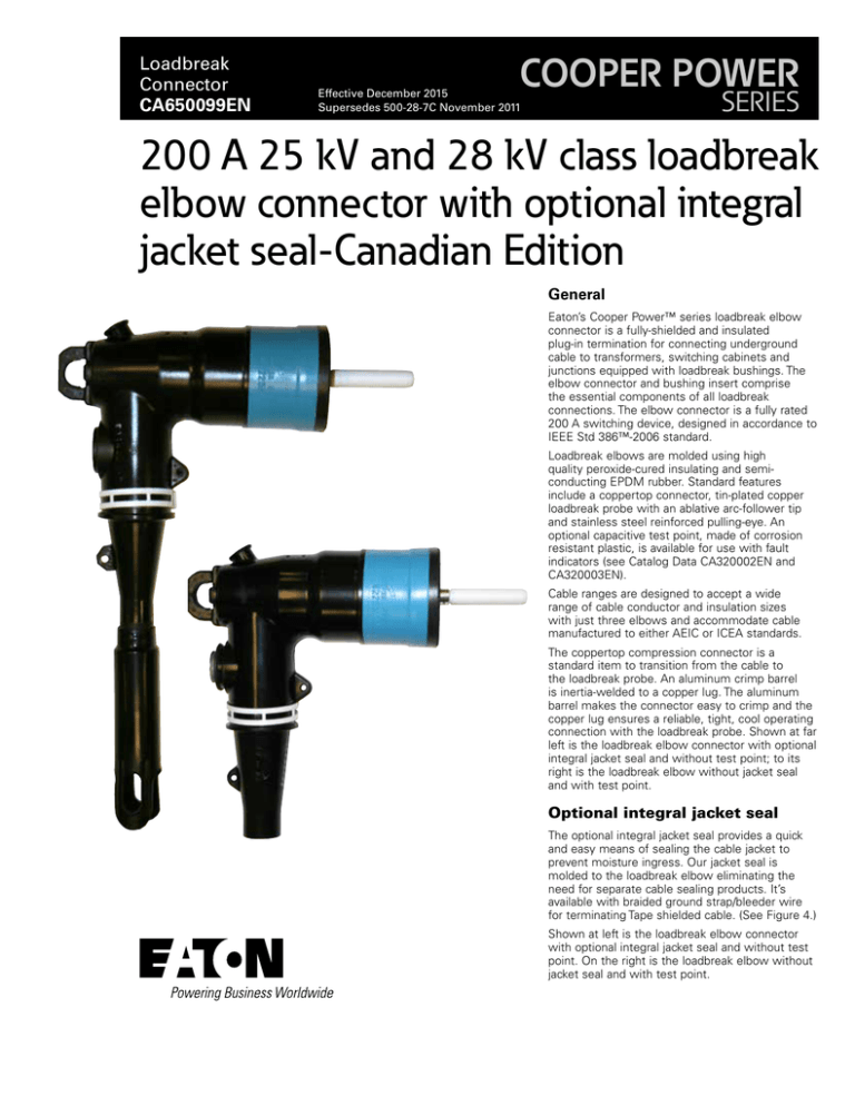
connection with the loadbreak probe. Shown at far
left is the loadbreak elbow connector with optional
integral jacket seal and without test point; to its
right is the loadbreak elbow without jacket seal
and with test point.
Optional integral jacket seal
The optional integral jacket seal provides a quick
and easy means of sealing the cable jacket to
prevent moisture ingress. Our jacket seal is
molded to the loadbreak elbow eliminating the
need for separate cable sealing products. It’s
available with braided ground strap/bleeder wire
for terminating Tape shielded cable. (See Figure 4.)
Shown at left is the loadbreak elbow connector
with optional integral jacket seal and without test
point. On the right is the loadbreak elbow without
jacket seal and with test point.
Catalog Data CA650099EN
Effective December 2015
SEMI-CONDUCTIVE INSERT
High-quality peroxide-cured EPDM rubber
creates a smooth surface around the
“current interchange” to evenly distribute
electrical stress within the insulation.
PULLING EYE
Stainless steel
reinforced for positive
clampstick switching
operations.
200 A 25 kV and 28 kV class loadbreak elbow connector
with optional integral jacket seal-Canadian Edition
INSULATION
High-quality peroxide-cured EPDM rubber formulated, mixed, and
milled in-house for consistent and reliable field performance.
SEMI-CONDUCTIVE SHIELD
High-quality peroxide-cured EPDM rubber
provides protective deadfront shield that
meets requirements of IEEE Std 592™2007 standard.
LOADBREAK PROBE
Tin-plated copper probe with arcablative tip (arc follower) provides
dependable loadbreak switching
characteristics.
TEST POINT (OPTIONAL)
Corrosion-resistant, conductive
electrode provides consistent
capacitive voltage for application
of fault indicators and determining
if the circuit is energized (cap not
shown).
LOADBREAK BAND
UV resistant nylon white/black/
white band identifies the elbow as
three-phase loadbreak rated and is
field replaceable.
Figure 1. Elbow cutaway illustrates design features.
2
www.eaton.com/cooperpowerseries
BLUE CUFF
Indicates 25 kV Class
COPPERTOP COMPRESSION CONNECTOR
Inertia-welded aluminum barrel and threaded copper lug makes
crimping easy and ensures a tight, reliable electrical connection with
loadbreak probe.
GROUNDING TABS
Molded into semi-conductive shield for the attachment of a
ground wire to maintain deadfront safety.
CONDUCTIVE INSERT ENDS
Encapsulated with insulating rubber.
Reduces cable extrusion and distortion that
can be caused by thermocycling. Mitigates
the effects of the electrical stresses
along the cable to elbow interface, greatly
reducing the possibility of interface
tracking.
Catalog Data CA650099EN
200 A 25 kV and 28 kV class loadbreak elbow connector
with optional integral jacket seal-Canadian Edition
Effective December 2015
S4
S3
S6
S
Dim.
25 kV
28 kV
S3
3.86”
(98.04 mm)
3.86”
(98.04 mm)
S4
4.54”
(115.32 mm)
4.54”
(115.32 mm)
S5
3.14”
(79.76 mm)
3.14”
(79.76 mm)
S6
1.64”
(41.66 mm)
1.64”
(41.66 mm)
S5
NNote: Dimensions given are for reference only.
Figure 2. Elbow profile and stacking dimensions as referenced in IEEE Std 386™-2006 standard.
Installation
Table 1. Voltage Ratings and Characteristics
Cable stripping and scoring tools, available from various tool
manufacturers, are recommended for use when installing loadbreak
elbows. After preparing the cable, the elbow housing is pushed
onto the cable. The loadbreak probe is threaded into the coppertop
connector using the supplied installation tool or an approved
equivalent. Use a clampstick to perform loadmake and loadbreak
operations. Refer to Service Information MN650008EN 200 A 15 kV
and 25 kV Class Elbow with Optional Integral Jacket Seal Installation
Instructions for details.
Description
Standard Voltage Class
Maximum Rating Phase-to-Phase
Maximum Rating Phase-to-Ground
AC 60 Hz 1 Minute Withstand
DC 15 Minute Withstand
BIL and Full Wave Crest
Minimum Corona Voltage Level
Production tests
25 kV
25
26.3
15.2
40
78
125
19
28 kV
28
28
16.2
45
100
125
21.5
Voltage ratings and characteristics are in accordance with IEEE Std 386™-2006 standard.
Tests conducted in accordance with IEEE Std 386™-2006 standard:
•
AC 60 Hz 1 Minute Withstand
• 25 kV=40 kV
•
•
Minimum Corona Voltage Level
• 25 kV=19 kV
•
•
28 kV=45 kV
Table 2. Current Ratings and Characteristics
Description
Continuous
Switching
Fault Closure
28 kV=21.5
Test Point Voltage Test
Tests conducted in accordance with Eaton requirements:
•
Physical Inspection
•
Periodic Dissection
•
Periodic Fluoroscopic Analysis
Short Time
25 kV
200 A rms
10 operations at 200 A rms at
26.3 kV
10,000 A rms symmetrical at
26.3 kV for 0.17 s after 10
switching operations
10,000 A rms symmetrical for
0.17 s
3,500 A rms symmetrical for
3.0 s
28 kV
200 A rms
10 operations at 200 A rms at
28.0 kV
10,000 A rms symmetrical at
28.0 kV for 0.17 s after 10
switching operations
10,000 A rms symmetrical for
0.17 s
3,500 A rms symmetrical for
3.0 s
Current ratings and characteristics are in accordance with IEEE Std 386™-2006 standard.
www.eaton.com/cooperpowerseries
3
Catalog Data CA650099EN
200 A 25 kV and 28 kV class loadbreak elbow connector
with optional integral jacket seal-Canadian Edition
Effective December 2015
Ordering information
METAL NEUTRAL
OR SHIELD
The elbow kits are packaged in a heavy duty
polyethylene bag. There are 20 bagged kits to a carton.
Individual boxed kits are also available by special part
number. To order a 25 kV or 28 kV Class Loadbreak
Elbow Kit follow the easy steps below.
DIAMETER OVER
OUTER JACKET
DIAMETER OVER
INSULATION
INSULATION
SHIELD
CONDUCTOR
Each kit contains:
•
Standard Elbow Body or Elbow Body with Jacket
Seal
•
Coppertop Compression Connector
•
Loadbreak Probe
•
Probe Installation Tool
•
Silicone Lubricant
•
Mastic Strips (Jacket Seal Elbow Only)
•
Installation Instruction Sheet
INSULATION
OUTER JACKET
CONDUCTOR
SHIELD
Figure 3. Illustration showing typical construction of medium voltage
underground cable.
STEP 5: For an elbow where a CSA connector was selected in Step
2, add “CSA” after the test point/no test point option.
STEP 1: Select required kV rating:
STEP 6: For optional braided ground strap/bleeder wire for
terminating tape shielded cable, Insert “GS” after test point and
CSA option code. (Integral Jacket Seal Elbow Only)
25 kV, LE225
28 kV, LE228
STEP 2: Determine the cable’s diameter over the electrical insulation
as shown in Figure 3 (including tolerances) from cable manufacturer.
Then identify a cable range from Table 3 that brackets the minimum
and maximum insulation diameters. Select the CABLE RANGE
CODE from the far right column.
STEP 7: (Optional) For an elbow kit individually packaged in a
corrugated cardboard box, insert an “X” as the last character in the
part number.
STEP 3: Identify the conductor size and type in Table 4 for
Standard IEEE compression connectors
Table 3. Cable Range for Loadbreak Elbow
Inches
Millimeters
Cable Range Code
OR
0.610” - 0.970”
15.5 - 24.6
AB
Table 5 for CSA compression connectors
0.750” - 1.080”
19.1 - 27.4
CC
0.890” - 1.220”
22.6 - 30.0
DD
AND
Select the CONDUCTOR CODE from the far right column.
* Uses 5 kV cable adapter.
STEP 4: For an elbow kit with a capacitive test point order:
(For use with “CC” range elbow only.)
LE225
LE228
CABLE RANGE
CODE
CONDUCTOR
CODE
T
For an elbow kit with integral jacket seal and capacitive test point
order:
LEJ225
LEJ228
CABLE RANGE
CODE
CONDUCTOR
CODE
T
For an elbow kit without a capacitive test point order:
LE225
LE228
CABLE RANGE
CODE
CONDUCTOR
CODE
For an elbow kit with integral jacket seal without a capacitive test
point order:
LEJ225
LEJ228
CABLE RANGE
CODE
CONDUCTOR
CODE
For an elbow kit without a compression connector, use “00” for the
conductor code.
4
www.eaton.com/cooperpowerseries
200 A 25 kV and 28 kV class loadbreak elbow connector
with optional integral jacket seal-Canadian Edition
Catalog Data CA650099EN
Effective December 2015
Table 4. Conductor Size and Type
Class B Stranded or
Compressed
AWG
No Connector
#6
#4
#3
#2
#1
1/0
2/0
3/0
4/0
250*
mm2
Compact or Solid
AWG
mm2
16
–
25
35
–
50
70
–
95
120
#4
#3
#2
#1
1/0
2/0
3/0
4/0
250
300
–
25
35
–
50
70
–
95
120
–
Conductor
Code
00
01
02
03
04
05
06
07
08
09
10
* Compressed stranding only.
NNote: Coppertop compression connector may be used on both aluminum and copper cable conductors.
Table 5. CSA Compression Connectors
Conductor Size and Type
Stranded
Concentric, Compressed or Compact
mm2
AWG
Solid
AWG
mm2
No Connector
Conductor
Code
00
#6
16
#4
–
01
#4
–
#3
–
02
#3
–
#2
25
03
#2
25
#1
35
04
#1
35
1/0
50
05
1/0
50
2/0
70
06
2/0
70
3/0
–
07
3/0
–
–
–
08
4/0
95
–
–
09
EXAMPLE: Select a 28 kV integral jacket seal elbow kit with CSA
connector and capacitive test point for use on a #1 compact cable
with a minimum insulation diameter of 0.770” and a maximum
diameter of 0.830”.
STEP 1: From Table 3, identify the cable range 0.750–1.080” and
select the “CC” CABLE RANGE CODE.
STEP 2: The conductor size is a #1 and the type is compact. CSA
style connector required.
From Table 5, under the column “Stranded” identify #1 and select
the “05” conductor code.
STEP 3: Order catalog number.
LEJ228CC05TCSA
www.eaton.com/cooperpowerseries
5
Catalog Data CA650099EN
200 A 25 kV and 28 kV class loadbreak elbow connector
with optional integral jacket seal-Canadian Edition
Effective December 2015
Table 6. Replacement CSA Coppertop Connectors
Table 7. Replacement Parts
Conductor Size and Type
Stranded
Concentric or Compressed
or Compact
Solid
Description
Catalog
Number
Hold Down Bail Assembly
2638351C01B
Loadbreak Probe Installation Tool
2602733A01
Loadbreak Probe Only
2637794B01
Probe Kit (includes Probe, Installation Tool, Silicone
Lubricant, Installation Instruction Sheet)
PK225
2603393A03
2605670A02M
AWG
mm2
AWG
mm2
Catalog
Number
#6
16
#4
–
CC2C01TCSA
#4
–
#3
–
CC2C02TCSA
#3
–
#2
25
CC2C03TCSA
#2
25
#1
35
CC2C04TCSA
Silicone Grease
0.175 oz tube (5 grams)
5.3 oz tube (150 grams)
#1
35
1/0
50
CC2C05TCSA
Test Point Cap
2639992A01
1/0
50
2/0
70
CC2C06TCSA
Includes Ground Braid, Constant Force Spring and Mastic
GRDBRAIDKIT
2/0
70
3/0
–
CC2C07TCSA
3/0
–
–
–
CC2C08TCSA
4/0
96
–
–
CC2C09TCSA
* Compressed stranding only.
NNote: Coppertop compression connector may be used on both aluminum and
copper cable conductors.
Accessories
Figure 4. Braided ground strap kit.
6
www.eaton.com/cooperpowerseries
200 A 25 kV and 28 kV class loadbreak elbow connector
with optional integral jacket seal-Canadian Edition
Catalog Data CA650099EN
Effective December 2015
This page intentionally left blank.
www.eaton.com/cooperpowerseries
7
Catalog Data CA650099EN
200 A 25 kV and 28 kV class loadbreak elbow connector
with optional integral jacket seal-Canadian Edition
Effective December 2015
Eaton
1000 Eaton Boulevard
Cleveland, OH 44122
United States
Eaton.com
Eaton’s Cooper Power Systems Division
2300 Badger Drive
Waukesha, WI 53188
United States
Eaton.com/cooperpowerseries
© 2015 Eaton
All Rights Reserved
Printed in USA
Publication No. CA650099EN
Eaton is a registered trademark.
All other trademarks are property
of their respective owners.
For Eaton's Cooper Power series product
information call 1-877-277-4636 or visit:
www.eaton.com/cooperpowerseries.

