Screened Separable
Connectors
CA650025EN
COOPER POWER
Electrical Apparatus
Effective May 2015
Supersedes April 2015
SERIES
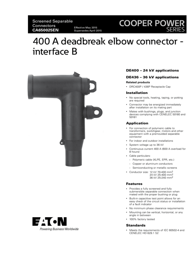
400 A deadbreak elbow connector interface B
DE400 – 24 kV applications
DE436 – 36 kV applications
Related products
•
DRC400P / 436P Receptacle Cap
Installation
•
No special tools, heating, taping, or potting
are required
•
Connector may be energized immediately
after installation on its mating part
•
Mates with bushings, plugs, and junction
devices complying with CENELEC 50180 and
50181
Application
•
For connection of polymeric cable to
transformers, switchgear, motors and other
equipment with a premoulded separable
connector
•
For indoor and outdoor installations
•
System voltage up to 36 kV
•
Continuous current 400 A (600 A overload for
8 hours)
•
Cable particulars:
• Polymeric cable (XLPE, EPR, etc.)
•
•
Copper or aluminum conductors
•
Semiconducting or metallic screens
Conductor size:12 kV 70-400 mm2
24 kV 25-400 mm2
36 kV 25-240 mm2
Features
•
Provides a fully screened and fully
submersible separable connection when
mated with the proper bushing or plug
•
Built-in capacitive test point allows for an
easy check of the circuit status or installation
of a fault indicator
•
No minimum phase clearance requirements
•
Mounting can be vertical, horizontal, or any
angle in between
•
100% factory tested
Standards
•
Meets the requirements of IEC 60502-4 and
CENELEC HD 629.1 S2
Catalog Data CA650025EN
400 A deadbreak elbow connector - interface B
Effective May 2015
Quality assurance
•
Table 1. Electrical Ratings
Our manufacturing facility is registered to ISO 9001 by third
party audit
•
Required Production Tests
•
Periodic X-Ray Analysis
Packaging
•
Supplied in a kit with all necessary parts, approximate weight
2 kg
3
DE400
DE436
Maximum System Voltage (Um)
24 kV
36 kV
Impulse
125 kV
170 kV
AC Withstand (5 min.)
54 kV
81 kV
Continuous Current
400 A
400 A
Overload (8 hrs. Max.)
600 A
600 A
Short Circuit Withstand, 1 sec. (rms sym)
18 kA
18 kA
NNote: Ratings are based on IEC Standards and do not reflect maximum
capability.
Features and detailed description
2
Description
1. Pin Contact
Tin-plated copper pin screws into the conductor contact with
the supplied hex key
1
2. Internal Screen
Moulded EPDM conducting rubber screen controls electrical
stress
4
3.Insulation
Moulded EPDM insulating rubber is formulated and mixed in
our facility in the USA to ensure high quality
4. Pulling Eye
Encapsulated Stainless Steel pulling eye with a detent to
position the bail
5
5. Capacitive Test Point
10
Capacitive test point provides means to check circuit status. A
moulded EPDM conducting rubber cap provides a watertight
seal.
6. Stress Relief
The configuration of the outer screen and the cable adapter
provide cable stress relief
9
7. Cable Adapter
The sized opening provides an interference fit to maintain a
watertight seal
8. Earthing Eye
8
6
Moulded into the external screen for connection of an
earthing wire
9. External Screen
Moulded EPDM conducting rubber mates with the cable
screen to maintain screen continuity and ensure that the
assembly is at earth potential
10. Conductor Contact
Inertia welded bimetallic compression connector accepts
copper or aluminum conductors
11. Stainless Steel Bail (Not Shown)
7
Secures the connector to its mating bushing or accessory
Figure 1. 400 A, 24/36 kV Class DE400/436 deadbreak elbow
connector.
2
www.eaton.com/cooperpowerseries
Catalog Data CA650025EN
400 A deadbreak elbow connector - interface B
Effective May 2015
83
mm
280 mm
100
MAX.
210* mm
195* mm
129
mm
250 mm
275 mm
Approximately
78
Dimensions in mm
* Add 100 mm to disconnect
115
MAX.
Figure 2. DE400 / 436 deadbreak connector dimensional information.
Ordering information
For 12 kV and 24 kV applications, the ordering formula is DE400R-C. for 36 kV applications, the ordering formula is DE436-R-C.
Substitute the R and C as described below. Select the range
from Table 2 that best fits the diameter of the core insulation.
Select the code from Table 3 for the conductor size and type of
connector required.
Table 2. Cable Insulation Range
Ordering Example: For 20 kV cable, 150 mm2 aluminum
conductor, 27.0 mm core insulation diameter, DIN connector,
specify DE400E150.
Cable seal adapters are ordered separately.
Table 3. Conductor Code
Stranded Conductor Size (mm2)
DIN Type
EDF Type
25
25
E25
Cable Insulation Range Ø (mm)
Insulation Range
Designation
35
35
E35
Min.
Max.
50
50
E50
AA
13.5
17.2
70
70
E70
A
16.3
19.3
95
95
E95
B
18.3
21.0
120
120
E120
C
20.0
24.1
150
150
E150
D
23.1
27.0
185
185
E185
E
25.6
29.0
240
240
E240
F
27.7
32.6
300
300
-
G
30.9
36.2
400
400
-
H
34.0
39.5
NNote: Bimetallic connectors can be used with aluminum or copper conductors.
Accessories
Description
Catalog Number
Bail Assembly
2638409C01B
www.eaton.com/cooperpowerseries
3
Catalog Data CA650025EN
400 A deadbreak elbow connector - interface B
Effective May 2015
Eaton
1000 Eaton Boulevard
Cleveland, OH 44122
United States
Eaton.com
Eaton’s Cooper Power Systems Division
2300 Badger Drive
Waukesha, WI 53188
Eaton.com/cooperpowerseries
© 2015 Eaton
All Rights Reserved
Printed in USA
Publication No. CA650025EN
Eaton and Cooper Power are valuable
trademarks of Eaton in the U.S. and other
countries. You are not permitted to use
these trademarks without the prior written
consent of Eaton.

