Deadbreak Connectors
Catalog Data
Effective August 2015
Supersedes 600-45 May 2002
CA650064EN
COOPER POWER
SERIES
600 A 15/25 kV class PUSH-OP®
insulated standoff bushing
General
Eaton's Cooper Power™ series 600 A, 15/25 kV
PUSH-OP® insulated standoff bushing meets the
full requirements of IEEE 386™-2006 standard
— Separable Insulated Connector Systems and
provides a single deadbreak interface made of high
quality insulating epoxy material.
It is used in switchgear, trans­form­ers, and other
apparatus to isolate and sectionalize an energized
cable. Temporary or permanent parking of
energized 600 A 15/25 kV PUSH-OP deadbreak
con­nec­tors is simplified with the use of an
insulated standoff bushing.
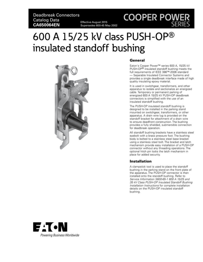
The PUSH-OP insulated standoff bushing is
de­signed to be installed in the parking stand
mounted on switch­gear, transformers, or other
apparatus. A drain wire lug is pro­vid­ed on the
standoff bracket for at­tach­ment of a drain wire
to ensure deadfront construction. The bushing
provides a fully shielded, submersible connection
for deadbreak operation.
All standoff bushing brackets have a stainless steel
eyebolt with a brass pressure foot. The bushing
body is bolted to a stainless steel base bracket
using a stainless steel bolt. The bracket and latch
mechanism provide easy installation of a PUSH-OP
connector without any threading operations. The
optional hitch pin locks the latch mechanism in
place for added security.
Installation
A clampstick tool is used to place the standoff
bushing in the parking stand on the front plate of
the apparatus. The PUSH-OP connector is then
installed onto the standoff bushing. Refer to
Service Information S600-65-1 600 A 15/25 and
35 kV Class PUSH-OP Insulated Standoff Bushing
Installation Instructions for complete installation
details on the PUSH-OP insulated standoff
bushing.
Catalog Data CA650064EN
600 A 15/25 kV class PUSH-OP insulated standoff bushings
Effective August 2015
Production tests
Ordering information
Tests are conducted in accordance with IEEE Std 386™-2006
standard.
To order a 15/25 kV Class Standoff Bushing Kit for the PUSH-OP
bushing, refer to Table 2.
•
ac 60 Hz 1 Minute Withstand
• 40 kV
Table 2. Standoff Bushing Kit
Description
Catalog Number
•
Minimum Corona Voltage Level
• 19 kV
Insulated Standoff Bushing
PISB625
Insulated Standoff Bushing with hitch Pin
PISB625HP
Tests are conducted in accordance with Eaton requirements.
•
Physical Inspection
Each kit contains:
•
Periodic Fluoroscopic Analysis
•
Standoff Bushing with Bracket
•
Shipping Cap (not for energized operation)
•
Silicone Lubricant
•
Installation Instruction Sheet
Table 1. Voltage Ratings and Characteristics–– Insulated
Standoff Bushing
Description
kV
Standard Voltage Class
25
Maximum Rating Phase-to-Ground
15.2
ac 60 Hz 1 Minute Withstand
40
dc 15 Minute Withstand
78
BIL and Full Wave Crest
125
Minimum corona voltage Level
19
Voltage ratings and characteristics are in accordance with IEEE Std 386™-2006 standard.
2
www.eaton.com/cooperpowerseries
Catalog Data CA650064EN
600 A 15/25 kV class PUSH-OP insulated standoff bushings
Effective August 2015
EYEBOLT
Stainless steel eyebolt with
brass pressure foot rigidly
secures standoff bushing to
parking stand.
4.0 "
(101.6 mm)
HITCH PIN
(optional) The hitch pin locks the
latch mechanism in place for
added security.
DEADBREAK
PUSH
HERE
PULLING EYE
Stainless steel eye
facilitates clampstick
operation with no
additional tool required.
STAINLESS STEEL
BRACKET AND LATCH
MECHANISM accepts 600 A
PUSH-OP connectors and
facilitates "threadless"
operability.
STAINLESS STEEL
BRACKET ASSEMBLY
Stainless steel
mounting bracket has
drain wire lug for
bracket and shield
grounding.
13 "
(330.2 mm)
EPOXY INSULATION
High quality molded epoxy
insulation provides excellent
electrical, thermal and
mechanical reliability for
insulated standoff bushings.
2.37 "
(60.2 mm)
DRAIN WIRE LUG
Provided for attachment
of drain wire lead.
5.25 "
(133.4 mm)
4.8 "
(121.9 mm)
5.50 "
(139.7 mm)
FRONT VIEW
SIDE VIEW
Figure 1. Front view shows standoff bushing and latch mechanism. Side view shows standoff bushing and latch mechanism with
bracket assembly.
NNote: Dimensions given are for reference only.
S8
S7
TANK
WALL
15/25 kV
S7
0.75" (19 mm)
S8
5.2" (131 mm)
Figure 2. PUSH-OP stacking dimensions.
www.eaton.com/cooperpowerseries
3
Catalog Data CA650064EN
600 A 15/25 kV class PUSH-OP insulated standoff bushings
Effective August 2015
Eaton
1000 Eaton Boulevard
Cleveland, OH 44122
United States
Eaton.com
Eaton’s Cooper Power Systems Division
2300 Badger Drive
Waukesha, WI 53188
United States
Eaton.com/cooperpowerseries
© 2015 Eaton
All Rights Reserved
Printed in USA
Publication No. CA650064EN
Eaton is a registered trademark.
All other trademarks are property
of their respective owners.
For Eaton's Cooper Power series standoff
bushing product information
call 1-877-277-4636 or visit:
www.eaton.com/cooperpowerseries.


