COOPER POWER SERIES installation and maintenance instructions
advertisement
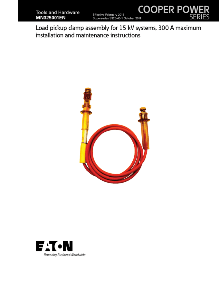
Tools and Hardware MN325001EN COOPER POWER Effective February 2015 Supersedes S325-40-1 October 2011 SERIES Load pickup clamp assembly for 15 kV systems, 300 A maximum installation and maintenance instructions DISCLAIMER OF WARRANTIES AND LIMITATION OF LIABILITY The information, recommendations, descriptions and safety notations in this document are based on Eaton Corporation’s (“Eaton”) experience and judgment and may not cover all contingencies. If further information is required, an Eaton sales office should be consulted. Sale of the product shown in this literature is subject to the terms and conditions outlined in appropriate Eaton selling policies or other contractual agreement between Eaton and the purchaser. THERE ARE NO UNDERSTANDINGS, AGREEMENTS, WARRANTIES, EXPRESSED OR IMPLIED, INCLUDING WARRANTIES OF FITNESS FOR A PARTICULAR PURPOSE OR MERCHANTABILITY, OTHER THAN THOSE SPECIFICALLY SET OUT IN ANY EXISTING CONTRACT BETWEEN THE PARTIES. ANY SUCH CONTRACT STATES THE ENTIRE OBLIGATION OF EATON. THE CONTENTS OF THIS DOCUMENT SHALL NOT BECOME PART OF OR MODIFY ANY CONTRACT BETWEEN THE PARTIES. In no event will Eaton be responsible to the purchaser or user in contract, in tort (including negligence), strict liability or otherwise for any special, indirect, incidental or consequential damage or loss whatsoever, including but not limited to damage or loss of use of equipment, plant or power system, cost of capital, loss of power, additional expenses in the use of existing power facilities, or claims against the purchaser or user by its customers resulting from the use of the information, recommendations and descriptions contained herein. The information contained in this manual is subject to change without notice. ii Load pickup clamp assembly for 15 kV systems installation and maintenance instructions MN325001EN February 2015 www.cooperpower.com Contents SAFETY INFORMATION Safety Information . . . . . . . . . . . . . . . . . . . . . . . . . . . . . . . . . . . . . . . . . . . . . . . . . . . . . . . . . . . . . . . . . . . . . . . . . . . . . . iv PRODUCT INFORMATION Introduction . . . . . . . . . . . . . . . . . . . . . . . . . . . . . . . . . . . . . . . . . . . . . . . . . . . . . . . . . . . . . . . . . . . . . . . . . . . . . . . . . . . 1 Acceptance and Initial Inspection . . . . . . . . . . . . . . . . . . . . . . . . . . . . . . . . . . . . . . . . . . . . . . . . . . . . . . . . . . . . . . . . . . 1 Handling and Storage . . . . . . . . . . . . . . . . . . . . . . . . . . . . . . . . . . . . . . . . . . . . . . . . . . . . . . . . . . . . . . . . . . . . . . . . . . . 1 Standards . . . . . . . . . . . . . . . . . . . . . . . . . . . . . . . . . . . . . . . . . . . . . . . . . . . . . . . . . . . . . . . . . . . . . . . . . . . . . . . . . . . . 1 APPLICATION INFORMATION Ratings . . . . . . . . . . . . . . . . . . . . . . . . . . . . . . . . . . . . . . . . . . . . . . . . . . . . . . . . . . . . . . . . . . . . . . . . . . . . . . . . . . . . . . . 2 INSTALLATION PROCEDURE Installation Procedure . . . . . . . . . . . . . . . . . . . . . . . . . . . . . . . . . . . . . . . . . . . . . . . . . . . . . . . . . . . . . . . . . . . . . . . . . . . 2 Load Pickup Clamp Assembly Installation . . . . . . . . . . . . . . . . . . . . . . . . . . . . . . . . . . . . . . . . . . . . . . . . . . . . . . . . . . . . 3 REMOVAL Load Pickup Assembly Removal . . . . . . . . . . . . . . . . . . . . . . . . . . . . . . . . . . . . . . . . . . . . . . . . . . . . . . . . . . . . . . . . . . . 5 INSPECTION AND MAINTENANCE Inspection and Maintenance . . . . . . . . . . . . . . . . . . . . . . . . . . . . . . . . . . . . . . . . . . . . . . . . . . . . . . . . . . . . . . . . . . . . . . 6 DISASSEMBLY Conductor Clamp and Upper Contact . . . . . . . . . . . . . . . . . . . . . . . . . . . . . . . . . . . . . . . . . . . . . . . . . . . . . . . . . . . . . . . 6 Handle Assembly . . . . . . . . . . . . . . . . . . . . . . . . . . . . . . . . . . . . . . . . . . . . . . . . . . . . . . . . . . . . . . . . . . . . . . . . . . . . . . . 8 Actuator Tube/Inner Tube Assembly . . . . . . . . . . . . . . . . . . . . . . . . . . . . . . . . . . . . . . . . . . . . . . . . . . . . . . . . . . . . . . . . . 9 Jumper Clamp . . . . . . . . . . . . . . . . . . . . . . . . . . . . . . . . . . . . . . . . . . . . . . . . . . . . . . . . . . . . . . . . . . . . . . . . . . . . . . . . 12 ASSEMBLY PROCEDURE Jumper Clamp . . . . . . . . . . . . . . . . . . . . . . . . . . . . . . . . . . . . . . . . . . . . . . . . . . . . . . . . . . . . . . . . . . . . . . . . . . . . . . . . 14 Load Pickup Clamp . . . . . . . . . . . . . . . . . . . . . . . . . . . . . . . . . . . . . . . . . . . . . . . . . . . . . . . . . . . . . . . . . . . . . . . . . . . . 14 STEPS FOR PICKUP CLAMPS WITH SLOTTED SCREWS Pickup Clamps with Slotted Screws . . . . . . . . . . . . . . . . . . . . . . . . . . . . . . . . . . . . . . . . . . . . . . . . . . . . . . . . . . . . . . .19 PARTS AND ACCESSORIES Load Pickup Clamp Assembly Parts . . . . . . . . . . . . . . . . . . . . . . . . . . . . . . . . . . . . . . . . . . . . . . . . . . . . . . . . . . . . . . . 21 Load pickup clamp assembly for 15 kV systems installation and maintenance instructions MN325001EN February 2015 www.cooperpower.com iii ! Safety for life SAFETY FOR LIFE ! SAFETY FOR LIFE Eaton’s Cooper Power™ series products meet or exceed all applicable industry standards relating to product safety. We actively promote safe practices in the use and maintenance of our products through our service literature, instructional training programs, and the continuous efforts of all Eaton employees involved in product design, manufacture, marketing, and service. We strongly urge that you always follow all locally approved safety procedures and safety instructions when working around high voltage lines and equipment, and support our “Safety For Life” mission. Safety information The instructions in this manual are not intended as a substitute for proper training or adequate experience in the safe operation of the equipment described. Only competent technicians who are familiar with this equipment should install, operate, and service it. Safety instructions Following are general caution and warning statements that apply to this equipment. Additional statements, related to specific tasks and procedures, are located throughout the manual. A competent technician has these qualifications: • Is thoroughly familiar with these instructions. • Is trained in industry-accepted high and low-voltage safe operating practices and procedures. • Is trained and authorized to energize, de-energize, clear, and ground power distribution equipment. • Is trained in the care and use of protective equipment such as arc flash clothing, safety glasses, face shield, hard hat, rubber gloves, clampstick, hotstick, etc. Following is important safety information. For safe installation and operation of this equipment, be sure to read and understand all cautions and warnings. Hazard Statement Definitions This manual may contain four types of hazard statements: DANGER Hazardous voltage. Contact with hazardous voltage will cause death or severe personal injury. Follow all locally approved safety procedures when working around highand low-voltage lines and equipment. G103.3 WARNING Before installing, operating, maintaining, or testing this equipment, carefully read and understand the contents of this manual. Improper operation, handling or maintenance can result in death, severe personal injury, and equipment damage. G101.0 WARNING Indicates an imminently hazardous situation which, if not avoided, will result in death or serious injury. This equipment is not intended to protect human life. Follow all locally approved procedures and safety practices when installing or operating this equipment. Failure to comply can result in death, severe personal injury and equipment damage. G102.1 WARNING WARNING DANGER Indicates a potentially hazardous situation which, if not avoided, could result In death or serious injury. CAUTION Indicates a potentially hazardous situation which, if not avoided, may result in minor or moderate injury. CAUTION: Indicates a potentially hazardous situation which, if not avoided, may result in equipment damage only. iv Power distribution and transmission equipment must be properly selected for the intended application. It must be installed and serviced by competent personnel who have been trained and understand proper safety procedures. These instructions are written for such personnel and are not a substitute for adequate training and experience in safety procedures. Failure to properly select, install or maintain power distribution and transmission equipment can result in death, severe personal injury, and equipment damage. G122.3 Load pickup clamp assembly for 15 kV systems installation and maintenance instructions MN325001EN February 2015 www.cooperpower.com Product Information Introduction Eaton's Cooper Power™ series load pickup clamp assembly installation instructions gives customers the ability and guidance to replace the load pickup clamp assembly. Read this manual first Handling and storage Be careful during handling and storage of the load pickup clamp assembly to minimize the possibility of damage. If the reversing stationary contacts are to be stored for any length of time prior to installation, provide a clean, dry storage area. Standards ISO 9001 Certified Quality Management System Read and understand the contents of this manual and follow all locally approved procedures and safety practices before installing or operating this equipment. Additional information These instructions cannot cover all details or variations in the equipment, procedures, or process described nor provide directions for meeting every possible contingency during installation, operation, or maintenance. For additional information, contact your representative. Acceptance and initial inspection Each load pickup clamp assembly is in good condition when accepted by the carrier for shipment. Upon receipt, inspect the shipping container for signs of damage. Unpack the load pickup clamp assembly and inspect it thoroughly for damage incurred during shipment. If damaged is discovered, file a claim with the carrier immediately. Load pickup clamp assembly for 15 kV systems installation and maintenance instructions MN325001EN February 2015 www.cooperpower.com 1 Application information Flexible jumper cable • WARNING Do not use between phases or as a grounding set. The Load Pickup Clamp assembly is intended for use as a temporary jumper to establish a circuit between energized and non-energized sections of a single phase. The Load Pickup Clamp Assembly is designed to pick up the electrical load that may be present in the non-energized section of the line, provided that: • • • Load is within specified limits-Maximum 300 A. Both the Load Pickup and Jumper Clamps in the set have been installed properly on the line Load Pickup Clamp contacts are actuated to the closed position WARNING The Load Pickup Clamp Assembly is designed for use on one phase of a distribution system in which the maximum phase-to-phase voltage is 15 kV. Maximum phaseto-ground voltage across the contacts of the Load Pickup Assembly must not exceed 8.3 kV. • Construction to conform to the latest applicable IPCEA S-19-81 NEMA® WC3 Specification Insulation and ampacity ratings to be compatible with the electrical circuit on which it is to be used. WARNING Load Pickup Clamp Assembly is not a loadbreak device. Prior to removal from the circuit and prior to the load pickup clamp assembly being opened, a solid parallel current path must be established. Table 1. Ratings Max. Current Rating* (A) Max. PhasetoGround Voltage Conductor Range Minimum 300 A 8.3 kV # 6 Sol. Conductor Range Maximum Jumper Cable** 800 KCMIL Str. or 795 KCMIL 26/7 ACSR # 2, 1/0 or 2/0 * Rating limited to the rating of cable installed. ** Use of cable not shown in table is not recommended. Maximum current should not exceed 300 amperes. Load Pickup Clamp Assembly is intended for use only in conjunction with and connected to a companion Jumper Clamp by means of a suitable length of Flexible Jumper Cable. 2 Load pickup clamp assembly for 15 kV systems installation and maintenance instructions MN325001EN February 2015 www.cooperpower.com Installation procedure Step 3 Load pickup clamp assembly installation Grip Handle of Load Pickup Clamp at "A" and turning clockwise, install the Load Pickup Clamp on the de‑energized line. See Figure 3. WARNING Assure that a fault condition does not exist prior to installation and that proper dielectric clearances are maintained to other energized or grounded components. Failure to comply could result in death or personal injury. Step 1 Set the Load Pickup Clamp in "Open" Position by gripping Actuator Tube at "B". Pull fully down to the "Stop". Turn to the right to the "Stop" and release. See Figure 1. Figure 2. Unthread the load pickup conductor clamp/ contact. WARNING A Do not use or hold the Actuator Tube when installing Load Pickup Clamp on the de-energized line. The Actuator Tube may trip the contact rod closing the circuit to the Jumper Clamp resulting in death or personal injury when the Jumper Clamp is installed. B Figure 1. Opening Load Pickup Clamp. Step 2 A Unthread Conductor Clamp/Contact of Load Pickup Clamp to clear the approximate diameter of the conductor to be installed on. See Figure 2. Figure 3. Installing Load Pickup Clamp on De-energized Line. Load pickup clamp assembly for 15 kV systems installation and maintenance instructions MN325001EN February 2015 www.cooperpower.com 3 Step 4 Step 6A Unthread Conductor Clamp of Jumper Clamp to the approximate diameter of the conductor to be installed. See Figure 4. Returning to the Load Pickup Clamp, grip the Actuator Tube at "B" then push and hold fully into the Handle to the stop. See Figure 6. Continue the operations as described in Step 6B. Figure 4. Unthread Conductor Clamp of Jumper Clamp. B Step 5 Grip the handle of the Jumper Clamp at "A" and turning clockwise, install the Jumper Clamp on the energized line. See Figure 5. Figure 6. Pushing the activator tube upward into the handle. Step 6B Turn the Actuator Tube to the left (as referenced when viewing the instruction label on the Actuator Tube) to initiate unrestricted, automatic closing. See Figure 7. A Figure 5. Installing the jumper clamp on the line. Figure 7. Initiating automatic closing. 4 Load pickup clamp assembly for 15 kV systems installation and maintenance instructions MN325001EN February 2015 www.cooperpower.com Removal Step 2 Load pickup assembly removal Grip handle of the Jumper Clamp at "A" and turning counter-clockwise, remove the Jumper Clamp from the line. See Figure 9. WARNING The Load Pickup Assembly is not a loadbreak device. Prior to removal from the circuit and prior to the Load Pickup Clamp being opened, a solid parallel current path must be established. Failure to comply may result in death or personal injury. A Step 1 Set the Load Pickup Clamp in "Open" Position by gripping the Actuator Tube at "B", pull fully down to the "Stop". Turn the Actuator to the right to the "Stop" and release. See Figure 8. Do not remove from line at this time. CAUTION Do not install or remove Load Pickup Clamp from the line with the contacts closed. This will cause unnecessary Contact and Contact Rod wear and possible damage. Figure 9. Removing the jumper clamp from the line. Step 3 Returning to the Load Pickup Clamp, grip the Handle at "A" and turning counter-clockwise, remove the Load Pickup Clamp from the line. See Figure 10. A B Figure 10. Removing the load pickup clamp from the unit. Figure 8. Opening the load pickup clamp. Load pickup clamp assembly for 15 kV systems installation and maintenance instructions MN325001EN February 2015 www.cooperpower.com 5 Inspection and maintenance Eaton recommends that an inspection and maintenance program be established. • • Ensure that each Load Pickup Clamp Assembly is thoroughly inspected after 25 operations or 90 days, whichever comes first. If used during adverse weather conditions, it is recommended that a full inspection is performed. Step 2 Clean Conductor Clamp and Upper Contact with Salisbury Solvent, #2002 or equivalent. See Figure 12. CAUTION Do not use solvents or any type of aerosol cleaners or lubricants on or near plastic parts. Use of solvents may compromise the integrity of the plastic parts. CAUTION Do not use solvents or any type of aerosol cleaners or lubricants on or near plastic parts. Use of solvents may compromise the integrity of the plastic parts. • Conductor Clamp During inspection/maintenance, the following parts should be disassembled: • Upper Contact • Handle Assembly • Actuator Tube • Inner Tube Assembly Load Pickup Clamp Assembly Disassembly Conductor clamp and upper contact Step 1 Make sure the Load Pickup Clamp is in the "Open" position. Unthread and remove the Conductor Clamp from the Load Pickup Clamp Assembly. See Figure 11. CAUTION Do not remove Load Pickup Conductor Clamp with the contacts closed. This will cause unnecessary Contact and Contact Rod wear and possible damage. Figure 11. Removing the conductor clamp from the assembly. Conductor Clamp Upper Contacts Figure 12. Cleaning conductor clamp and upper contacts. 6 Load pickup clamp assembly for 15 kV systems installation and maintenance instructions MN325001EN February 2015 www.cooperpower.com Step 3 Step 5 Inspect Conductor Clamp and Upper Contacts for cracks or breaks. See Figure 13. Lubricate Multi-lam Contact with Eaton's Cooper Power series Kearney™ Contact Lubricant, Catalog #132488. See Figure 15. WARNING Conductor Clamps and Upper Contacts with cracks or breaks should be replaced. Failure to comply could result in personal injury or death. Inspect for Cracks Figure 15. Lubricate Contacts. Step 6 Close Load Pickup Clamp Contact Assembly. See Figure 16. Figure 13. Conductor Clamp and upper contacts. Step 4 Use gauge to ensure proper sizing of Multi-lam Contact. See Figure 14. Figure 16. Closing the contact assembly. Figure 14. Gauge Contacts. Load pickup clamp assembly for 15 kV systems installation and maintenance instructions MN325001EN February 2015 www.cooperpower.com 7 Handle assembly Step 9 Remove the Handle. See Figure 19. Step 7 Remove both of the Handle Assembly screw caps. See Figure 17. Handle Figure 17. Removing the screw caps. Figure 19. Removing handle from assembly. Step 8 Using a 5/32" (or 4 mm) hex, remove both of the Handle Assembly hex screws. See Figure 18. • Hex Screw • Clean Handle with warm, soapy water (or mild detergent) to remove carbon/soot and other contaminants. Inspect the Handle for cracks or chips. WARNING Extensive carbon buildup is a likely sign that the Load Pickup Assembly has been used as a loadbreak device and the device shall be removed from service. CAUTION Do not use solvents or any type of aerosol cleaners or lubricants on or near plastic parts. Use of solvents may compromise the integrity of the plastic parts. Figure 18. Removing the handle hex screws. WARNING Handle Assemblies with cracks or chips should be replaced. Failure to comply could result in equipment fracture, personal injury or death. 8 Load pickup clamp assembly for 15 kV systems installation and maintenance instructions MN325001EN February 2015 www.cooperpower.com Step 12 Actuator tube/inner tube assembly Remove Contact Rod and Spring from the Inner Tube. See Figure 22. Step 10 Remove the Inner Tube Cap from the Inner Tube Assembly. See Figure 20. • Inspect Contact Rod —Plating - Ensure that the plating is still present on the Contact Road and in good condition. If the plating is in poor condition, the Contact Rod should be replaced. —Scratches - If extensive scratches are present, the Contact Rod should be replaced. Inner Tube Cap • • Inspect the Spring and measure the free length. Replace if the Spring shows signs of damage or the free length is not between 10.5 and 11.3 inches. Clean the Contact Rod and the Spring with Salisbury Cleaner, #2002 or equivalent. CAUTION Do not use solvents or any type of aerosol cleaners or lubricants on or near plastic parts. Use of solvents may compromise the integrity of the plastic parts. Figure 20. Removing inner tube cap. CAUTION Because the Contact Rod/Spring in the Inner Tube Assembly is under tension, care must be taken to secure the Contact Rod prior to removal of the screw to prevent the Contact Rod and Spring from rapidly exiting the Inner Tube Assembly. Spring Contact Rod Assembly Inner Tube Step 11 Secure Contact Rod, and determine: A. If the Load Pickup Clamp has a slotted screw, remove the screw and proceed to Steps for Pickup Clamps with Slotted Screws page 19. B. If the Load Pickup Clamp has a screw with internal hex use a 1/8" (3 mm) hex key, remove the screw holding Actuator Tube and Inner Tube Assembly together. See Figure 21. Inner Tube Actuator Tube Figure 22. Inner tube assembly components. Actuator Tube Figure 21. Unfastening actuator tube from inner tube assembly. Load pickup clamp assembly for 15 kV systems installation and maintenance instructions MN325001EN February 2015 www.cooperpower.com 9 Step 13 Step 15 Slide the Actuator Tube back onto the cable. See Figure 23. Using a 15/16" wrench and pliers, loosen the lock nut on the ferrule. See Figure 25. Actuator Tube Inner Tube Figure 23. Sliding the actuator tube onto the cable. Figure 25. Loosening the lock nut. Step 14 Using a 3/32" hex, remove the set screw from the ferrule. See Figure 24. Step 16 Unthread the Inner Tube Assembly from the ferrule. See Figure 26. Cable Ferrule Figure 24. Removing the set screw from the ferrule. 10 Figure 26. Removing the inner tube from the ferrule. Load pickup clamp assembly for 15 kV systems installation and maintenance instructions MN325001EN February 2015 www.cooperpower.com Step 17 Step 19 Remove the Lower Contacts from the Inner Tube. See Figure 27. Inspect Lower Contacts. See Figure 29. L-slot Inner Tube Lower Contacts Figure 29. Inspect Lower Contacts. Figure 27. Removing lower contact from inner tube. • Step 20 Use gauge to ensure proper sizing of Multi-lam Contact. See Figure 30. Clean the Inner Tube and Inner Tube Cap with warm soapy water (or mild detergent) to remove carbon/soot or other contaminants. CAUTION Do not use solvents or any type of aerosol cleaners or lubricants on or near plastic parts. Use of solvents may compromise the integrity of the plastic parts. • Inspect the Inner Tube and the Inner Tube cap for cracks and chips, paying special attention to the L-slot areas. See Figure 27 for location of L-slot. WARNING Inner Tubes with cracks or chips shall be replaced. Failure to comply could result in equipment fracture, personal injury or death. Step 18 Figure 30. Gauge Lower Contacts. Step 21 Lubricate Multi-lam Contact with Kearney Contact Lubricant, Catalog #132488. See Figure 31. Clean the Lower Contacts with Salisbury Cleaner #2002 or equivalent. See Figure 28. Figure 31. Lubricate Lower Contacts. Figure 28. Cleaning Lower Contacts. Load pickup clamp assembly for 15 kV systems installation and maintenance instructions MN325001EN February 2015 www.cooperpower.com 11 Jumper clamp Step 22 Slide the Actuator Tube off of the cable. See Figure 32. Step 24 Unthread and remove the Conductor Clamp from the Actuator Tube Conductor Clamp Jumper Clamp Assembly Figure 32. Removing actuator tube from the cable. Figure 34. Removing the conductor clamp from the jumper clamp. • Clean the Actuator Tube with warm, soapy water (or mild detergent) to remove soot and other contaminants. CAUTION Do not use solvents or any type of aerosol cleaners or lubricants on or near plastic parts. Use of solvents may compromise the integrity of the plastic parts. • Jumper Clamp Assembly. See Figure 34. Step 25 Using a 1/8" hex wrench, remove the hex screw from the Jumper Conductor Clamp. See Figure 35. Inspect the Actuator Tube for cracks or chips. WARNING Actuator Tubes with cracks or breaks shall be replaced. Failure to comply could result in fracture of the actuator tube, personal injury or death. Step 23 Inspect the cable and ferrule for cable strand damage. See Figure 33. Cables with strand damage should be replaced. Inspect for Cable Strand Damage Conductor Clamp Hex Screw Figure 35. Removing the hex screw. Figure 33. Inspecting the cable. 12 Load pickup clamp assembly for 15 kV systems installation and maintenance instructions MN325001EN February 2015 www.cooperpower.com Step 26 Using a 15/16" wrench and pliers, remove the Jumper Conductor Clamp from the cable ferrule. See Figure 36. Figure 36. Removing the conductor clamp from the cable ferrule. • • Clean the Conductor Clamp with Salisbury Cleaner #2002 or equivalent. Inspect the Conductor Clamp for cracks or breaks. WARNING The Conductor Clamps with cracks or breaks shall be replaced. Failure to comply could result in equipment fracture, personal injury or death. Step 27 Inspect cable and ferrule for the cable strand damage. Cables with strand damage should be replaced. See Figure 37. Inspect for Cable Strand Damage Figure 37. Inspecting the cable. Load pickup clamp assembly for 15 kV systems installation and maintenance instructions MN325001EN February 2015 www.cooperpower.com 13 Assembly procedure Step 3 Thread the Conductor Clamp onto the Jumper Clamp Assembly. See Figure 40. Jumper clamp Step 1 Thread the Conductor Clamp onto the cable ferrule and align the hole with the flat on the ferrule. Using a 1/8" hex wrench, install the hex set screw and tighten. See Figure 38. Figure 40. Installing the conductor clamp onto the jumper clamp assembly. Load pickup clamp Step 4 Go to the opposite end of the cable. Figure 38. Installing the conductor clamp on the ferrule. Slide the Actuator Tube onto the cable. See Figure 41. Actuator Tube Step 2 Cable Using a 15/16" wrench, tighten the ferrule locknut and washer against Conductor Clamp. See Figure 39. Figure 41. Installing the actuator tube on the cable. Figure 39. Securing the conductor clamp on the ferrule. 14 Load pickup clamp assembly for 15 kV systems installation and maintenance instructions MN325001EN February 2015 www.cooperpower.com Step 5 Step 8 Insert the lower contact into the Inner Tube. See Figure 42. Using a 15/16" wrench, tighten the ferrule locknut against the bottom of the Lower Contact. See Figure 45. Threaded End Figure 42. Inserting the contact into the inner tube. Step 6 Thread the Lower Contact and Inner Tube onto the cable ferrule and align the hole with the flat on the ferrule. See Figure 43. Figure 45. Tightening the ferrule locknut. Step 9 Insert the Contact Rod, Spring (large end first) and Inner Tube cap into the Inner Tube. See Figure 46. Small End of Spring Figure 43. Installing the inner tube on the cable ferrule. Step 7 Using a 5/32" hex wrench, install the hex screw and tighten. See Figure 44. Figure 46. Installing the contact rod, spring and inner tube cap. Figure 44. Installing the hex screw. Load pickup clamp assembly for 15 kV systems installation and maintenance instructions MN325001EN February 2015 www.cooperpower.com 15 Step 10 Step 12 Apply tension to the Contact Rod/Spring and align the threaded hole in the Contact Rod Collar with the slot in the Inner Tube. See Figure 47. Apply a small amount of Loctite® 242 threadlocker to the threads of the screw. NNote: Avoid contacting the plastic parts with Loctite. Any deposits should be wiped up immediately. Using a 1/8" (3 mm) hex key, thread the screw in and tighten. See Figure 49. Figure 47. Aligning the contact rod in the inner tube. Figure 49. Installing and tightening the screw. Step 11 Slide the Actuator Tube forward, lining the slot up with the slot in the Inner Tube and threaded hole in the Contact Rod Collar. See Figure 48. Step 13 Install the Handle. See Figure 50. Figure 50. Installing the handle. Figure 48. Aligning the actuator tube with inner tube and contact rod collar. 16 Load pickup clamp assembly for 15 kV systems installation and maintenance instructions MN325001EN February 2015 www.cooperpower.com Step 14 Step 16 Align the holes in the handle with the holes in the inner tube assembly. Place the Contact Assembly in the open position. See Figure 53. • Using a 5/32" hex, install both the Handle hex screws. Torque to 40 in-lbs maximum. See Figure 51. Align Holes with Holes in Inner Tube Assembly Figure 53. Opening the contact assembly. Figure 51. Installing the handle hex screws. Step 17 Thread the Conductor Clamp into the Handle Assembly. See Figure 54. Step 15 Install both Handle screw caps. See Figure 52. Conductor Clamp Handle Assembly Figure 54. Installing the conductor clamp onto the handle. Figure 52. Installing the screw caps. CAUTION Do not thread or unthread the Conductor Clamp with the Contacts in a closed position. This will cause unnecessary Contact/Contact Rod wear and possible damage. Load pickup clamp assembly for 15 kV systems installation and maintenance instructions MN325001EN February 2015 www.cooperpower.com 17 Step 18 Close the Contact Assembly. See Figure 55. Figure 55. Closing the contact assembly. Step 19 Open and close the Contact Assembly several times to ensure the Load Pickup Clamp is operating properly. Step 20 Close Contact Assembly. Assure electrical continuity through the use of an ohmmeter. Step 21 Open Contact Assembly. With the conductor clamp fully tightened, assure voltage withstand of 15 kV (DC Hi-Pot test) for one minute. 18 Load pickup clamp assembly for 15 kV systems installation and maintenance instructions MN325001EN February 2015 www.cooperpower.com Steps for pickup clamps with slotted screws Step 2 Step 1 Old design - Replace with a new collar by following Steps 23 through 25. Remove Contact Rod and Spring from the Inner Tube. See Figure 56. • Inspect the Contact Rod Assembly and determine if the collar is the old or new design. See Figure 57. New design - Proceed to Step 26 on page 13. Inspect Contact Rod –– Plating - Ensure that the plating is still present on the Contact Rod and in good condition. If the plating is in poor condition, the Contact Rod should be replaced. –– Scratches - If extensive scratches are present, the Contact Rod should be replaced. • • Inspect the Spring for any damage and replace as necessary. Clean the Contact Rod and the Spring with Salisbury Cleaner, #2002 or equivalent. Chamfered Outer Edges CAUTION Do not use solvents or any type of aerosol cleaners or lubricants on or near plastic parts. Use of solvents may compromise the integrity of the plastic parts. Figure 57. New collar to the left. Note the chamfered outer edges. Spring Contact Rod Assembly Step 3 Inner Tube If the screw has broken off, replace the complete Contact Rod Assembly (Catalog Number 132479CPS). See Figure 58. Actuator Tube Figure 56. New collar to the left. Note the chamfered outer edges. Figure 58. Contact Rod Assembly with broken screw. Load pickup clamp assembly for 15 kV systems installation and maintenance instructions MN325001EN February 2015 www.cooperpower.com 19 Step 4 Step 6 Remove one of the retainers with the help of two flat head screw drivers as shown. If a vise is used, be sure to protect the rod from damage by using a soft cloth or some other protection between the jaws of the vise and the Contact Rod surface. Remove the collar. See Figure 59. To test the new collar and screw, insert a new screw (see Step 14A) and tighten. If the collar spins freely on the Contact Rod, the parts are good and the completed assembly will work correctly. Remove the screw and set it aside. It will be used later in the Reassembly Procedure. See Figure 61. NNote: If the collar doesn't spin freely, remove the screw and replace it with a new screw. If it still doesn't work, replace the collar and discard. Check the assembly again by following the above procedures. Figure 59. Removing the retaining ring. Figure 61. Check the installation of a new collar and screw. Step 5 Slide a new Collar onto the Contact Rod and re-install the retaining ring(s). A pair of pliers may be helpful in pushing the retainer back into the groove on the Contact Rod. Make sure all three tabs on the retaining ring are seated in the groove. If the retaining ring is bent, replace it with a new retaining ring, Catalog Number 64184-2. See Figure 60. Step 7 Slide the copper washer over the long end of the Contact Rod Assembly followed by the small end of the spring. See Figure 62. NNote: If the spring has never been replaced or it was a long time (five years or more) since it was last replaced, this would be a good time to replace the spring as well. Spring Catalog Number: 13916-2 Figure 60. Re-installing the retaining ring. Figure 62. Installing the spring on the Contact Rod Assembly. Continue the dis-assembly process in Step 13 on Page 10. 20 Load pickup clamp assembly for 15 kV systems installation and maintenance instructions MN325001EN February 2015 www.cooperpower.com Parts and accessories 11 8 12 12 7 11 19 9 10 1 6 14 15 3 2D 2B 2A 2 16 17 5 20 21 Opposite Label 1A 2C 13 22 4 18 Figure 63. Load Pickup Clamp Assembly parts breakdown. Load pickup clamp assembly for 15 kV systems installation and maintenance instructions MN325001EN February 2015 www.cooperpower.com 21 Table 1. Parts and Accessories Load Pickup Clamp and Cable 1 132476-4 Inner Tube 1A 134595 Inner Tube Cap 2 132479CPS Contact Rod Assembly Includes: 2A 134345 Contact Rod 2B 64184-2 Ring Retainer 2C 134346 Collar 2D 279634-1 Washer 3 13916-2 Spring 4 0839869A03 Set Screw with Hex 5 132499 Contact Tube Assembly 6 760401310018R Set Screw, 10-32 x 3/16 7 132480-1 Load Pickup Handle Assembly 8 132498 Conductor Clamp with Cap 9 134598-1 Outer Handle Tube 10 16649-1 Cap Only 11 66107-2 Hole Plug 12 733601125050R Flat Head Screw 13 134352-1 Actuator Tube 14 3806-002 Cable #2 (Specify length) 14 3806-010 Cable 1/0 (Specify length) 14 3806-020 Cable 2/0 (Specify length) 15 30365-1 Ferrule Assembly for #2 Cable 15 30365-2 Ferrule Assembly for #1/0 Cable 15 30365-3 Ferrule Assembly for #2/0 Cable 16 880615111062R Nut, Hex Jam SS 5/8-11 17 900815062000R Lock Washer 5/8 18 1330-263 Decal, Warning 19 1939981A01 Decal, Caution 20 1330-269 Decal, Large 21 1330-236 Decal, Small 22 1330-217 Decal, “OPEN” Jumper Clamp* (132284) Jumper Clamp Handle Assembly 1 132284JH (Items 2, 3 and 4 not included) 2 16644-28 Brass Contact Body 3 16649-1 Rubber Cap 4 760415125018R Set Screw 1/4-20 x 3/16 Not Pictured SK31479-2 Multi-Lam Contact Gauge Not Pictured 132488 Contact Lubricant Accessories * Not pictured. 22 Load pickup clamp assembly for 15 kV systems installation and maintenance instructions MN325001EN February 2015 www.cooperpower.com This page is intentionally left blank. Load pickup clamp assembly for 15 kV systems installation and maintenance instructions MN325001EN February 2015 www.cooperpower.com 23 ! SAFETY FOR LIFE Eaton 1000 Eaton Boulevard Cleveland, OH 44122 United States Eaton.com Eaton’s Cooper Power Systems Division 2300 Badger Drive Waukesha, WI 53188 United States Cooperpower.com © 2015 Eaton All Rights Reserved Printed in USA Publication No. MN325001EN Rev 00 Supersedes S325401CPS Rev 04 Eaton. Cooper Power, and Kearney are valuable trademarks of Eaton, in the U.S. and other countries. You are not permitted to use these trademarks without the prior written consent of Eaton. NEMA® is a registered trademark of the National Electrical Manufacturers Association. Loctite® is a registered trademark of Henkel Corporation. For Eaton's Cooper Power series load pickup clamp assembly product information call 1-877-277-4636 or visit: www.cooperpower.com.
